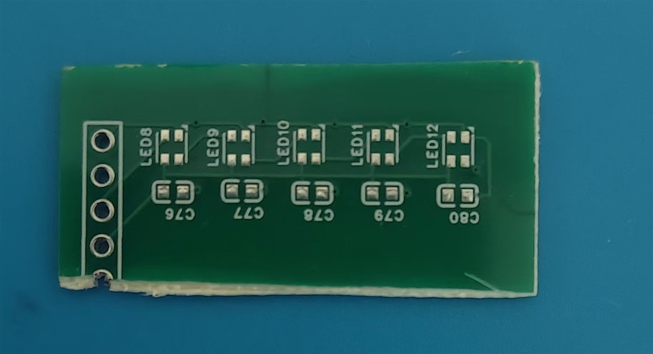
element14 Community
element14 Community
    Register Log In
  • Site
  • Search
  • Log In Register
  • Community Hub
    Community Hub
    • What's New on element14
    • Feedback and Support
    • Benefits of Membership
    • Personal Blogs
    • Members Area
    • Achievement Levels
  • Learn
    Learn
    • Ask an Expert
    • eBooks
    • element14 presents
    • Learning Center
    • Tech Spotlight
    • STEM Academy
    • Webinars, Training and Events
    • Learning Groups
  • Technologies
    Technologies
    • 3D Printing
    • FPGA
    • Industrial Automation
    • Internet of Things
    • Power & Energy
    • Sensors
    • Technology Groups
  • Challenges & Projects
    Challenges & Projects
    • Design Challenges
    • element14 presents Projects
    • Project14
    • Arduino Projects
    • Raspberry Pi Projects
    • Project Groups
  • Products
    Products
    • Arduino
    • Avnet & Tria Boards Community
    • Dev Tools
    • Manufacturers
    • Multicomp Pro
    • Product Groups
    • Raspberry Pi
    • RoadTests & Reviews
  • About Us
  • Store
    Store
    • Visit Your Store
    • Choose another store...
      • Europe
      •  Austria (German)
      •  Belgium (Dutch, French)
      •  Bulgaria (Bulgarian)
      •  Czech Republic (Czech)
      •  Denmark (Danish)
      •  Estonia (Estonian)
      •  Finland (Finnish)
      •  France (French)
      •  Germany (German)
      •  Hungary (Hungarian)
      •  Ireland
      •  Israel
      •  Italy (Italian)
      •  Latvia (Latvian)
      •  
      •  Lithuania (Lithuanian)
      •  Netherlands (Dutch)
      •  Norway (Norwegian)
      •  Poland (Polish)
      •  Portugal (Portuguese)
      •  Romania (Romanian)
      •  Russia (Russian)
      •  Slovakia (Slovak)
      •  Slovenia (Slovenian)
      •  Spain (Spanish)
      •  Sweden (Swedish)
      •  Switzerland(German, French)
      •  Turkey (Turkish)
      •  United Kingdom
      • Asia Pacific
      •  Australia
      •  China
      •  Hong Kong
      •  India
      •  Korea (Korean)
      •  Malaysia
      •  New Zealand
      •  Philippines
      •  Singapore
      •  Taiwan
      •  Thailand (Thai)
      • Americas
      •  Brazil (Portuguese)
      •  Canada
      •  Mexico (Spanish)
      •  United States
      Can't find the country/region you're looking for? Visit our export site or find a local distributor.
  • Translate
  • Profile
  • Settings
Light Up Your Life
  • Challenges & Projects
  • Design Challenges
  • Light Up Your Life
  • More
  • Cancel
Light Up Your Life
Forum Smart car chamber #4 Control Communication Protocols on SIX WL-ICLED Integrated Controller LEDs
  • News
  • Forum
  • Projects
  • DC
  • Leaderboard
  • Files
  • Members
  • More
  • Cancel
  • New
Join Light Up Your Life to participate - click to join for free!
Actions
  • Share
  • More
  • Cancel
Forum Thread Details
  • Replies 2 replies
  • Subscribers 48 subscribers
  • Views 88 views
  • Users 0 members are here
Related

Smart car chamber #4 Control Communication Protocols on SIX WL-ICLED Integrated Controller LEDs

fyaocn
fyaocn 10 days ago

1 Arrival of PCBs

With easyEDA, PCB for  six PCB for SIX WL-ICLED Integrated Controller LED are designed and just arrived recently as Smart car chamber #3 Comparisons of WL-ICLED Integrated Controllers and schematic designs - element14 Communit 

imageimageimageimageimage

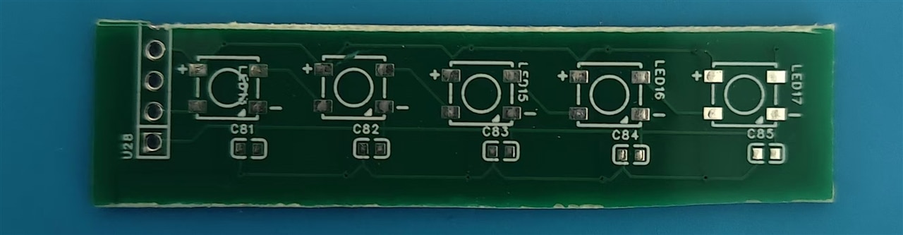
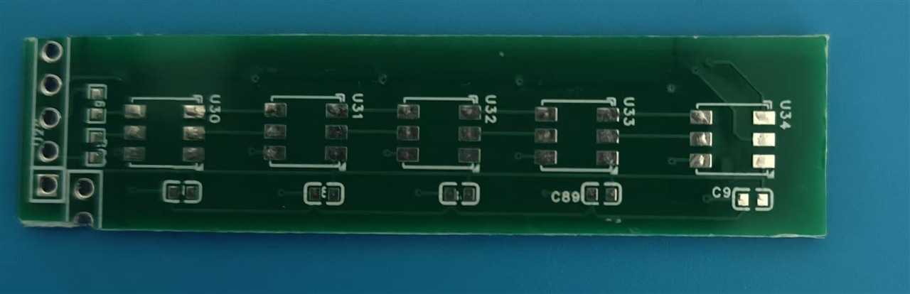
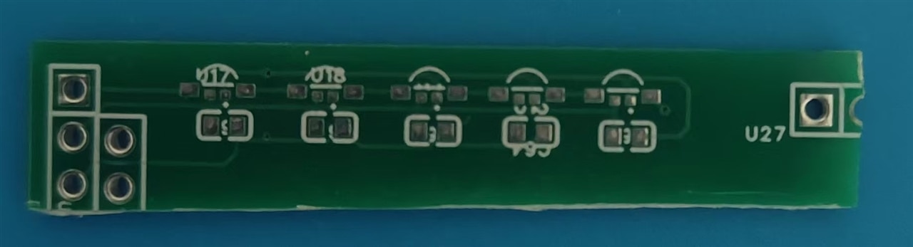
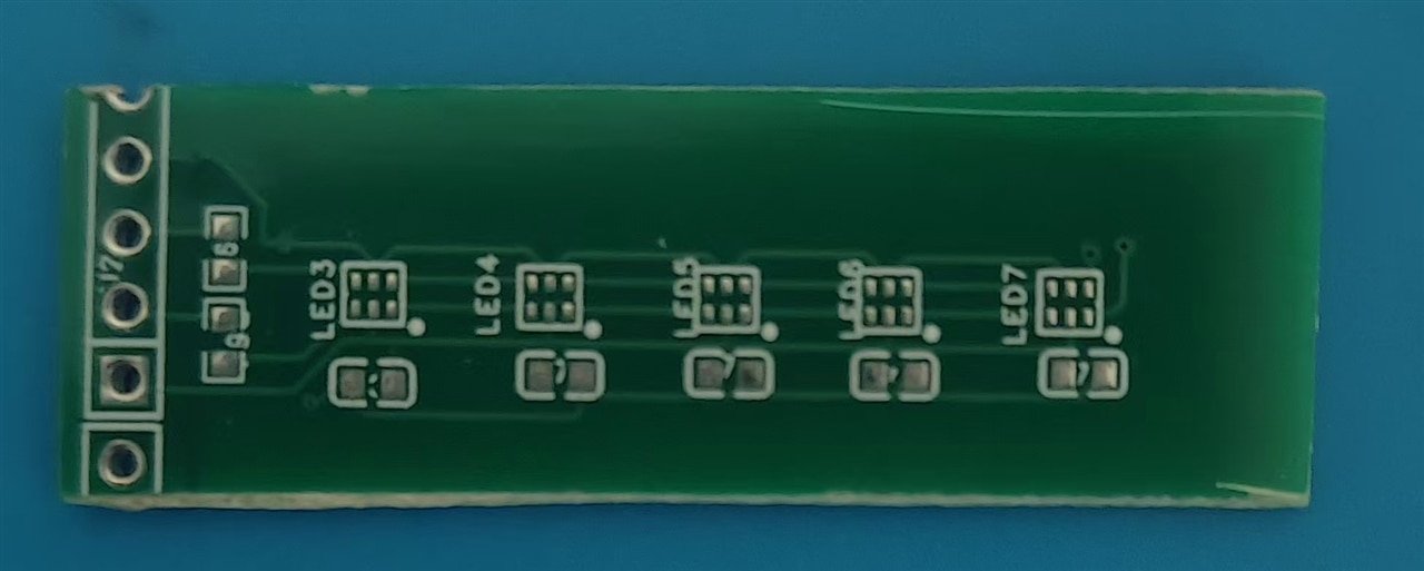
There are various type in desgin and basically  fit for different Control Communication Protocols. 

2 Analysis of Differences in Control Communication Protocols 

The six WL-ICLED integrated controller LEDs (Order Numbers: 1311610030140, 1312020030000, 1312121320437, 1313210530000, 1315050930002, 1315050930246) exhibit core differences in their control communication protocols across four key dimensions: data frame structure, command control capability, synchronization mechanism, and dimming precision.

The specific variations are detailed below:

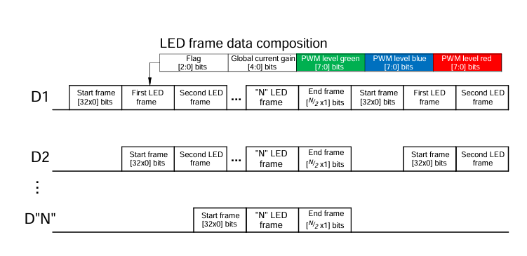
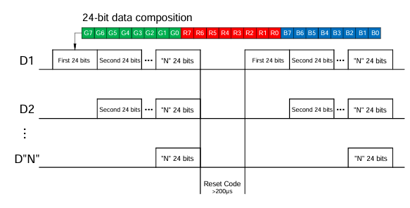
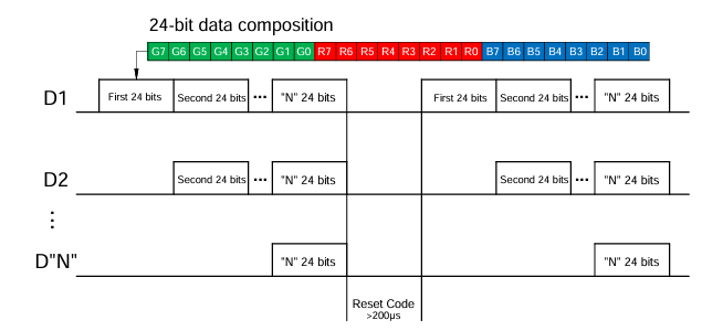
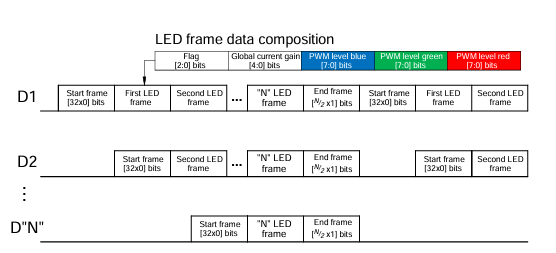
2.1 Differences in Data Frame Structure: Varied Bit Widths and Content Arrangement

The data frame serves as the core carrier of the protocol. The frame structures of the six products can be categorized into three types: "32-bit start frame + LED frame", "24-bit simplified frame", and "48-bit high-precision frame".
Protocol Type Corresponding Order Number Frame Structure Details Core Features
32-bit Start Frame + LED Frame 1311610030140, 1315050930246 1. Overall frame sequence: 32-bit start frame (fixed as 32 "0"s) + "N" LED frames (N = number of LEDs) + [N/2 "1"s] end frame
2. Single LED frame content:
- 1311610030140: 3 flag bits + 5 global current gain bits + 8 green PWM bits + 8 blue PWM bits + 8 red PWM bits
- 1315050930246: 3 flag bits + 5 global current gain bits + 8 blue PWM bits + 8 green PWM bits + 8 red PWM bits (only PWM color order adjusted)
Complex frame structure with a complete "start-data-end" sequence; supports unified adjustment of global current.
24-bit Simplified Frame 1312020030000, 1313210530000, 1315050930002 1. No start/end frames; only a single 24-bit data frame
2. Frame content: 8 green PWM bits (G7-G0) + 8 red PWM bits (R7-R0) + 8 blue PWM bits (B7-B0)
Extremely simple structure; no additional control bits; focuses solely on RGB PWM dimming.
48-bit High-Precision Frame 1312121320437 1. No start/end frames; only a single 48-bit data frame
2. Frame content: 4 red current gain bits + 12 red PWM bits + 4 green current gain bits + 12 green PWM bits + 4 blue current gain bits + 12 blue PWM bits
Longest bit width; supports "independent current gain + high-precision PWM"; highest dimming precision.

2.2 Differences in Command Control Capability: Varied Functional Complexity

The command control capabilities of the six products are divided into two levels: "full-function commands" and "no additional commands". Differences focus on support for sleep/wake-up, current gain adjustment, and other functions.
Command Capability Level Corresponding Order Number Supported Command Types Functional Limitations
Full-Function Commands 1311610030140, 1315050930246 1. Sleep mode command: Set flag bits to 3‘b101 to activate sleep mode (current level selector and PWM level must be set to 0 simultaneously)
2. Main register command: Set flag bits to 3‘b111 to configure current magnitude and PWM level
3. Wake-up mechanism: Wake-up time is approximately 1ms when a new flag bit is received and the current level selector value ≠ 0xA0
4. Reserved commands: Flag bits 3‘b000-3‘b100 and 3‘b110 are reserved and do not support functions temporarily
Supports low-power sleep and flexible parameter configuration; suitable for scenarios requiring power control.
No Additional Commands 1312020030000, 1312121320437, 1313210530000, 1315050930002 1. No sleep/wake-up commands or global configuration commands
2. Brightness and color adjustment only via PWM bits and current gain bits in the data frame:
- 24-bit frame products (e.g., 1312020030000): Only 8-bit PWM adjustment
- 48-bit frame product (1312121320437): 4-bit independent current gain + 12-bit PWM adjustment
Extremely simple functions; only meets basic dimming needs; no power control capability.

2.3 Differences in Synchronization Mechanism: Varied Reset Pulses and Frame Synchronization Methods

The synchronization mechanism determines the stability of data transmission in multi-LED cascading. The synchronization methods of the six products are divided into two types: "frame sequence synchronization" and "reset pulse synchronization".
Synchronization Type Corresponding Order Number Synchronization Details Applicable Scenarios
Frame Sequence Synchronization 1311610030140, 1315050930246 1. No additional reset pulses required; synchronization is achieved via a fixed data stream sequence ("32-bit start frame (32x0) + LED frames + end frame (N/2x1)")
2. In multi-LED cascading, the controller automatically identifies start/end frames to distinguish data for different LEDs
Flexible cascading quantity; no additional synchronization signals needed; suitable for complex LED arrays.
Reset Pulse Synchronization 1312020030000, 1312121320437, 1313210530000, 1315050930002 1. No fixed frame sequence; synchronization relies entirely on external reset pulses:
- 1312020030000, 1313210530000, 1315050930002: Reset pulse duration > 200μs
- 1312121320437: Reset pulse duration ≥ 50μs
2. In multi-LED cascading, a reset pulse must be sent before each data transmission round to avoid data misalignment
Synchronization depends on external pulses; suitable for simple cascading (e.g., ≤ 10 LEDs).

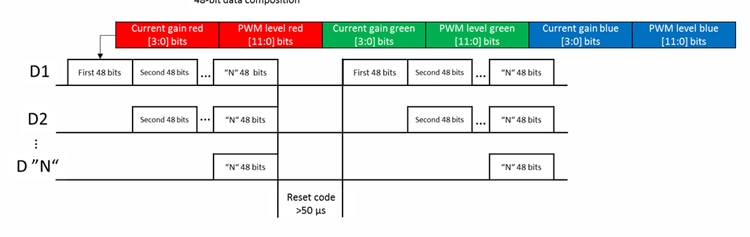
2.4  Differences in Dimming Precision: Varied PWM Bit Widths and Current Control Granularity

Dimming precision directly affects the subtlety of color and brightness. The precision differences of the six products are reflected in PWM bit width and current gain control methods.
Precision Level Corresponding Order Number Dimming Parameter Details Precision Performance
Basic Precision 1312020030000, 1313210530000, 1315050930002 1. PWM bit width: 8 bits (256 dimming levels per color)
2. No current gain control; current is fixed by supply voltage and internal circuits
Fewer brightness adjustment levels (256 levels); no current fine-tuning capability; suitable for scenarios with low precision requirements (e.g., ambient lights).
Medium Precision 1311610030140, 1315050930246 1. PWM bit width: 8 bits (256 dimming levels per color)
2. Current control: 5-bit global current gain (32 adjustment levels); all colors share the same gain value
256 brightness levels; supports 32-level global current fine-tuning; suitable for scenarios requiring unified current adjustment (e.g., smart home panels).
High Precision 1312121320437 1. PWM bit width: 12 bits (4096 dimming levels per color)
2. Current control: 4-bit independent current gain (16 adjustment levels); red, green, and blue colors are adjusted independently
Extremely high number of brightness adjustment levels (4096 levels); supports independent current fine-tuning for single colors; suitable for professional scenarios (e.g., stage lighting, display devices).

3 Core differences and data transmission diagram 

3.1 Cross-checkTable 

Difference Dimension 1311610030140 1312020030000 1312121320437 1313210530000 1315050930002 1315050930246
Data Frame Structure 32-bit start frame + LED frame (3+5+8+8+8 bits) 24-bit (8+8+8 bits) 48-bit (4+12+4+12+4+12 bits) 24-bit (8+8+8 bits) 24-bit (8+8+8 bits) 32-bit start frame + LED frame (3+5+8+8+8 bits, different PWM order)
Command Control Supports sleep/wake-up, global current adjustment No additional commands No additional commands; supports independent current adjustment No additional commands No additional commands Supports sleep/wake-up, global current adjustment
Synchronization Method Frame sequence synchronization (no reset pulse) Reset pulse (>200μs) Reset pulse (≥50μs) Reset pulse (>200μs) Reset pulse (>200μs) Frame sequence synchronization (no reset pulse)
Dimming Precision 8-bit PWM + 5-bit global gain 8-bit PWM 12-bit PWM + 4-bit independent gain 8-bit PWM 8-bit PWM 8-bit PWM + 5-bit global gain

3.2 Detail diagram

data transmission diagram 1311610030140

image

data transmission diagram 1312020030000

image

data transmission diagram 1312121320437

image

data transmission diagram 1313210530000

image

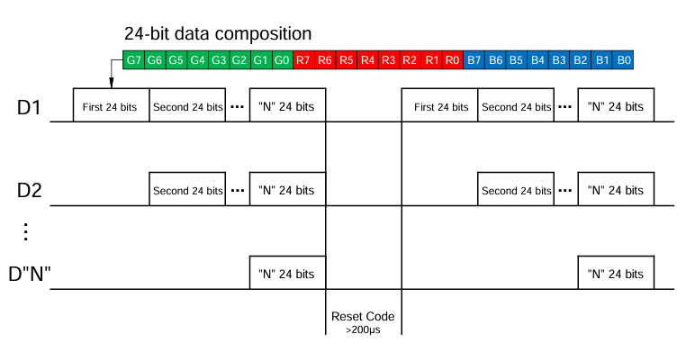
data transmission diagram 1315050930002

image

data transmission diagram 1315050930246

image

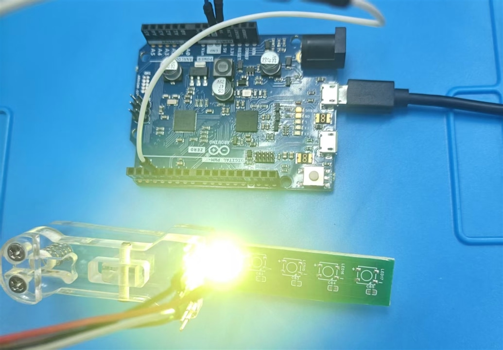
4 Blink the LED with Arduino FastLED library 

The have been example for Arduino FastLED library. The simpliest application is same as that of WS2816

image

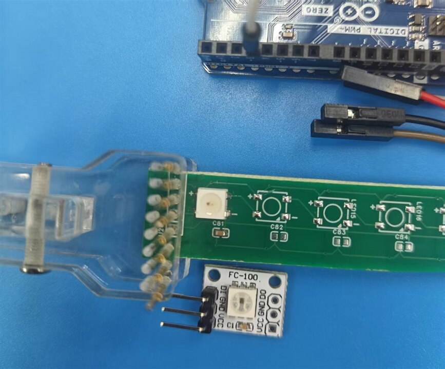
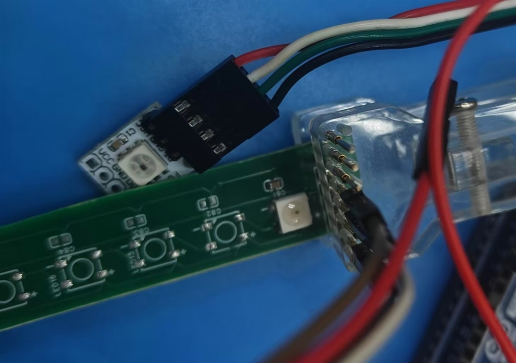
For start-up, start from 1312020030000, the 4-pins LED size of 50x50 , with only one welding on board, wiring with test clips

image

Other types of WL-ICLED shall be tested after welding on boards.

5 The control pin matters a lot

At first, the WL-ICLED is welded with this simple welding plate, good for LED removal, But some pin is not fixed in good position, the WL-ICLED light up without blinking.

image

Then I hand weld again, it works fine.

image

You don't have permission to edit metadata of this video.
Edit media
x
image
Upload Preview
image

The data in pin is important, it outputs command for LED illumination control. If it is removed, the state of led is not changed again, it stale in on state of off state only.

You don't have permission to edit metadata of this video.
Edit media
x
image
Upload Preview
image
You don't have permission to edit metadata of this video.
Edit media
x
image
Upload Preview
image

6 Control two led strips

If two led strips to be controlled , only two pins from MCU is needed. It can be controlled easily just as this blink example.

You don't have permission to edit metadata of this video.
Edit media
x
image
Upload Preview
image

7 Next post

Put all the LED on PCB boards is what in next post. Use different technique as comparation.

  • Sign in to reply
  • Cancel

Top Replies

  • JoRatcliffe
    JoRatcliffe 9 days ago +2
    I am glad your PCBs arrived great photos and videos!
Parents
  • DAB
    DAB 9 days ago

    Nice update.

    • Cancel
    • Vote Up 0 Vote Down
    • Sign in to reply
    • Cancel
Reply
  • DAB
    DAB 9 days ago

    Nice update.

    • Cancel
    • Vote Up 0 Vote Down
    • Sign in to reply
    • Cancel
Children
No Data
element14 Community

element14 is the first online community specifically for engineers. Connect with your peers and get expert answers to your questions.

  • Members
  • Learn
  • Technologies
  • Challenges & Projects
  • Products
  • Store
  • About Us
  • Feedback & Support
  • FAQs
  • Terms of Use
  • Privacy Policy
  • Legal and Copyright Notices
  • Sitemap
  • Cookies

An Avnet Company © 2025 Premier Farnell Limited. All Rights Reserved.

Premier Farnell Ltd, registered in England and Wales (no 00876412), registered office: Farnell House, Forge Lane, Leeds LS12 2NE.

ICP 备案号 10220084.

Follow element14

  • X
  • Facebook
  • linkedin
  • YouTube