


Last week I posted about the design and construction of the front panel for the vintage toy synthesiser, however another thing I had been doing alongside that is putting together the electronics and software for allowing the synthesis engine to be controlled by the panel controls. This ended up being a bit of a nightmare to get working well as I'll talk about below, but I think I've finally got it into a stable state. A lot of the electronics and software for the panel is very similar to that of the key mechanism of the synth, therefore I will often refer to the blogpost on that within this post rather than repeating myself.
Electronics
Components used:
- Potentiometer, 10K, regular (x 35)
- Potentiometer, 10k, centre-detented (x 7)
- Toggle Switch
- Resistor, 10k
- Ceramic capacitor, 0.1uF (x 4)
- MC14067 multiplexer (x 3)
- Arduino Pro Mini (3.3V version)
- DIP24 0.6" IC socket (x 4)
Controls
As mentioned in a previous blogpost the only controls I am using on my panel are potentiometers/dials and a toggle switch, simply because these are the most useful and common controls that are used in similar projects and products.
Potentiometers
I decided to only use dial pots instead of slider pots as they take up less room on the panel. I am using pots with a value of 10k as this is recommended pot to use when just using a microcontroller to read its value. I am also using a few centre-detented pots for the bipolar depth controls so that the user can easily centre these values. I had considered using centre-detented pots for a few of the other parameters (oscillator coarse tune, pulse amount, keyboard octave and transpose) however from testing these pots they often don't actually centre on the exact central value, which would not work with these particular parameters which are quite coarse.
I have connected the pots to the circuit in the standard way - the two outer pins go to power and ground and the centre pin goes to an analogue input (which in my case is on a multiplexer).
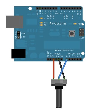
A potentiometer connected directly to an Arduino. Source: https://www.arduino.cc/en/Tutorial/AnalogReadSerial
Toggle Switch
The switch I am using is a SPST (Single Pole, Single Throw) switch, which is all that is needed when wanting to read a switch/button value using a microcontroller.
I have connected the toggle switch to the circuit in a standard way, using a 10k pull-down resistor so that when the switch is off it gets pulled to ground to produce a value of LOW. However as all my multiplexers are connected to analogue inputs the switch is connected to an analogue input instead of a digital input, but this just mean I'll get a value of 0 or 1023 instead of LOW or HIGH.
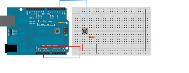
A button connected to an Arduino. Source: https://www.arduino.cc/en/Tutorial/Button
Microcontroller and Multiplexers
Just like with the synths key mechanism, I am using a 3.3V Arduino Pro Mini microcontroller for reading the control values which are then send to the BBB via serial. See the key mechanism production blogpost for more info on this design decision. However there are a couple of changes I have made here compared to that of the key mech:
- I am using 16-channel multiplexers instead of 8-channel multiplexers. This is simply because I am not able to get enough analogue inputs for all 43 panel controls using 8-channel muxes with an Arduino Pro Mini (well that's what I thought at the time of developing this circuit, however since then I have learnt that that's not the case, which I've talked about below in the 'Alternative Circuit Design' section).
- All the muxes and the Arduino are attached to the circuit via DIP IC sockets. I did this so that these components can be easily replaced if they break, which is something I learnt the hard way with the key mech circuit (I have actually since gone back and added this to the key mech circuit).
- All the muxes (as well as the VCC signal to the pots) have had 0.1uf decoupling capacitors added to them - something that digital circuits should have which I wasn't aware of (another thing that I have since gone back and added to the key mech circuit).
The Completed Circuit
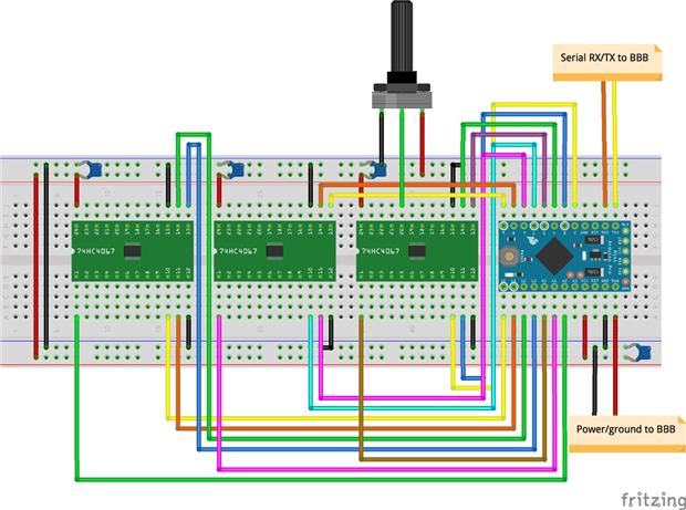
The completed circuit for the panel has been developed using stripboard which will be screwed to the underside of the panel using standoffs, using solid core wire to make all connections. Below is a breadboard diagram of the circuit but with only one potentiometer attached:
Here are some photos of the completed circuit:
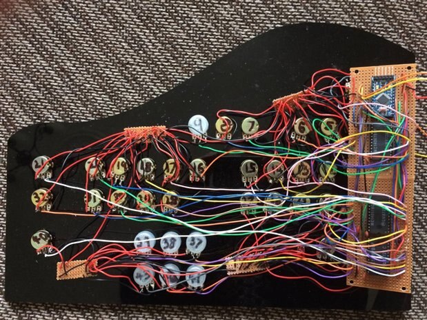
The completed vintage toy synth panel circuit

The potentiometers and toggle switch connected to the panel
It's not my neatest or prettiest wiring, though unfortunately if attempting to develop a circuit that contains 42 potentiometers on stripboard instead of a PCB there are going to be lots of wires.
Alternative Circuit Design
As with the key mech circuit, within the panel circuit each mux uses its own set of digital and analogue pins on the Arduino, meaning that in total I've used 12 digital pins (4 digital outs as the control/select inputs for each mux) and 3 analogue pins (1 analogue output from each mux). At the time of developing this circuit I thought that this was the only way it could be done, however since then I've discovered through one of my superiors that it can be done using less Arduino pins, meaning that I could have used cheaper 8-channel muxes (such as 4051s) and still able to get enough analogue inputs. This can be done by sharing the digital pins between the muxes (connecting the same 4 digital outs to all of the mux select/control pins), which can be done as I only need to read from one mux at a time. This can be taken a step further by using only one analogue input on the Arduino and sharing it between all the muxes, using the mux inhibit pins to only turn on one mux at a time. Therefore using these two methods I could change this panel circuit to only use 7 digital pins (4 for the mux control/select inputs, and 3 for each of the muxes inhibit pins) and 1 analogue pin (for the analogue output coming from each mux).
The main benefit to this alternative circuit design is that it allows you to add more inputs/outputs to your microcontrollers, which is very useful when using boards such as the Arduino Pro Mini which only has a limited number of them. For example, using these two methods with an Arduino pro mini, which has 12 digital pins (ignoring the serial RX and TX pins) and 8 analogue pins (which can be used as digital pins if needed), it would be possible to have a total of 128 analogue inputs using 16 8-channel 4051 muxes, or 240 analogue inputs/outputs using 15 16-channel 4067 muxes! However the main downside to these methods is that they are more prone to errors such as reading from multiple muxes at the same time, so you need to be extra careful in the software that you are definitely turning off one mux before you start reading from the next one.
Software
As mentioned above, all the reading of controls is handled using an Arduino microcontroller, so the only software required for the front panel is a single Arduino sketch that needs to handle two things - reading value changes from the controls, and sending these changes to the BBB as serial-based MIDI messages.
The panel software is a lot less complex than that of the key mechanism. All it needs to do is read the state of every pot and switch, and if it reads a new/changed value for a controls it converts it into the range of the sound parameter it is controlling and sends the value to the BBB via serial as a MIDI message. The MIDI message used by the panel are Control Change (CC) messages, where the first byte is 176 + MIDI channel (always 0 in this case), the second byte is a control number, and third byte is control value. Each parameter within the synth has it's own MIDI CC controller number, which is used within the panel and the BBB software for accessing and setting the parameters value. It can also be used by external MIDI gear for controlling that parameter externally, or for controlling external MIDI gear using the synths panel. I haven't yet offically documented the MIDI CC specification of the synth, however you can see a list of the CCs in the globals.h file.
I have created a GitHub repository to host all my code and schematics/diagrams for this project. To see the up-to-date panel code click here, or for the code at the time of writing this blogpost see below.
/*
   Vintage Toy Synthesiser Project - panel code.


   This the code for the Arduino Pro Mini attached to the piano's panel.
   This particular code is for using up to 4 16-channel multiplexers.


   All pins are used for the following:
   2 - 5: Mux1 select output pins
   6 - 9: Mux2 select output pins
   10 - 13: Mux3 select output pins
   A4 - A7 (as digital outputs): Mux4 select output pins
   A0: Mux1 input pin
   A1: Mux2 input pin
   A3: Mux3 input pin
   A4: Mux4 input pin


   Note that Mux4 may not be connected, but this code allows for it to be
   used. Mux4 mist be connected if NUM_OF_CONTROLS is greater than 16 * 3.


   //REMEMBER THAT ANY SERIAL DEBUGGING HERE MAY SCREW UP THE SERIAL COMMS TO THE BBB!
*/


//==========================================


//The number of pots/switches attached
const byte NUM_OF_CONTROLS = 43;


//for dev
const byte FIRST_CONTROL = 0;
const byte LAST_CONTROL = 42;


//The previous anologue value received from each control
int prevAnalogueValue[NUM_OF_CONTROLS] = {0};
//The previous param/MIDI value sent by each control
byte prevParamValue[NUM_OF_CONTROLS] = {0};


//MIDI channel we want to use
const byte midiChan = 0;


const byte VAL_CHANGE_OFFSET = 8;


//==========================================
//param data for each control


struct ControlParamData
{
  const byte cc_num;
  const byte cc_min_val;
  const byte cc_max_val;
  const bool is_depth_param;
};


ControlParamData controlParamData[NUM_OF_CONTROLS] =
{
  {.cc_num = 74, .cc_min_val = 0, .cc_max_val = 127, false}, //0 - PARAM_FILTER_CUTOFF
  {.cc_num = 19, .cc_min_val = 0, .cc_max_val = 127, false}, //1 - PARAM_FILTER_RESO
  {.cc_num = 26, .cc_min_val = 0, .cc_max_val = 127, false}, //2 - PARAM_FILTER_LP_MIX
  {.cc_num = 28, .cc_min_val = 0, .cc_max_val = 127, false}, //3 - PARAM_FILTER_HP_MIX
  {.cc_num = 27, .cc_min_val = 0, .cc_max_val = 127, false}, //4 - PARAM_FILTER_BP_MIX
  {.cc_num = 29, .cc_min_val = 0, .cc_max_val = 127, false}, //5 - PARAM_FILTER_NOTCH_MIX
  {.cc_num = 50, .cc_min_val = 0, .cc_max_val = 3, false}, //6 - PARAM_LFO_SHAPE
  {.cc_num = 47, .cc_min_val = 0, .cc_max_val = 127, false}, //7 - PARAM_LFO_RATE
  {.cc_num = 48, .cc_min_val = 0, .cc_max_val = 127, true}, //8 - PARAM_LFO_DEPTH
  {.cc_num = 14, .cc_min_val = 0, .cc_max_val = 127, false}, //9 - PARAM_OSC_SINE_LEVEL
  {.cc_num = 15, .cc_min_val = 0, .cc_max_val = 127, false}, //10 - PARAM_OSC_TRI_LEVEL
  {.cc_num = 16, .cc_min_val = 0, .cc_max_val = 127, false}, //11 - PARAM_OSC_SAW_LEVEL
  {.cc_num = 18, .cc_min_val = 0, .cc_max_val = 127, false}, //12 - PARAM_OSC_SQUARE_LEVEL
  {.cc_num = 17, .cc_min_val = 0, .cc_max_val = 127, false}, //13 - PARAM_OSC_PULSE_LEVEL
  {.cc_num = 3, .cc_min_val = 0, .cc_max_val = 127, false}, //14 - PARAM_OSC_PULSE_AMOUNT
  {.cc_num = 7, .cc_min_val = 0, .cc_max_val = 127, false}, //15 - PARAM_AEG_AMOUNT
  {.cc_num = 73, .cc_min_val = 0, .cc_max_val = 127, false}, //16 - PARAM_AEG_ATTACK
  {.cc_num = 75, .cc_min_val = 0, .cc_max_val = 127, false}, //17 - PARAM_AEG_DECAY
  {.cc_num = 79, .cc_min_val = 0, .cc_max_val = 127, false}, //18 - PARAM_AEG_SUSTAIN
  {.cc_num = 72, .cc_min_val = 0, .cc_max_val = 127, false}, //19 - PARAM_AEG_RELEASE
  {.cc_num = 13, .cc_min_val = 0, .cc_max_val = 127, false}, //20 - PARAM_FX_DISTORTION_AMOUNT
  {.cc_num = 33, .cc_min_val = 40, .cc_max_val = 88, false}, //21 - PARAM_OSC_SINE_NOTE
  {.cc_num = 34, .cc_min_val = 40, .cc_max_val = 88, false}, //22 - PARAM_OSC_TRI_NOTE
  {.cc_num = 35, .cc_min_val = 40, .cc_max_val = 88, false}, //23 - PARAM_OSC_SAW_NOTE
  {.cc_num = 37, .cc_min_val = 40, .cc_max_val = 88, false}, //24 - PARAM_OSC_SQUARE_NOTE
  {.cc_num = 36, .cc_min_val = 40, .cc_max_val = 88, false}, //25 - PARAM_OSC_PULSE_NOTE
  {.cc_num = 20, .cc_min_val = 0, .cc_max_val = 127, false}, //26 - PARAM_OSC_PHASE_SPREAD
  {.cc_num = 22, .cc_min_val = 0, .cc_max_val = 127, false}, //27 - PARAM_FEG_ATTACK
  {.cc_num = 23, .cc_min_val = 0, .cc_max_val = 127, false}, //28 - PARAM_FEG_DECAY
  {.cc_num = 24, .cc_min_val = 0, .cc_max_val = 127, false}, //29 - PARAM_FEG_SUSTAIN
  {.cc_num = 25, .cc_min_val = 0, .cc_max_val = 127, false}, //30 - PARAM_FEG_RELEASE
  {.cc_num = 107, .cc_min_val = 0, .cc_max_val = 127, false}, //31 - PARAM_GLOBAL_VINTAGE_AMOUNT
  {.cc_num = 102, .cc_min_val = 0, .cc_max_val = 7, false}, //32 - PARAM_KEYS_SCALE
  {.cc_num = 114, .cc_min_val = 61, .cc_max_val = 67, false}, //33 - PARAM_KEYS_OCTAVE
  {.cc_num = 106, .cc_min_val = 58, .cc_max_val = 70, false}, //34 - PARAM_KEYS_TRANSPOSE
  {.cc_num = 103, .cc_min_val = 0, .cc_max_val = 127, false}, //35 - PARAM_VOICE_MODE
  {.cc_num = 58, .cc_min_val = 0, .cc_max_val = 127, true}, //36 - PARAM_MOD_LFO_AMP
  {.cc_num = 112, .cc_min_val = 0, .cc_max_val = 127, true}, //37 - PARAM_MOD_LFO_CUTOFF
  {.cc_num = 56, .cc_min_val = 0, .cc_max_val = 127, true}, //38 - PARAM_MOD_LFO_RESO
  {.cc_num = 9, .cc_min_val = 0, .cc_max_val = 100, false}, //39 - PARAM_GLOBAL_VOLUME
  {.cc_num = 63, .cc_min_val = 0, .cc_max_val = 127, true}, //40 - PARAM_MOD_VEL_AMP
  {.cc_num = 109, .cc_min_val = 0, .cc_max_val = 127, true}, //41 - PARAM_MOD_VEL_CUTOFF
  {.cc_num = 110, .cc_min_val = 0, .cc_max_val = 127, true}, //42 - PARAM_MOD_VEL_RESO
};


//FOR DEVELOPMENT
//ControlParamData controlParamData[NUM_OF_CONTROLS] =
//{
//
//   {.cc_num = 0, .cc_min_val = 0, .cc_max_val = 127},
//   {.cc_num = 1, .cc_min_val = 0, .cc_max_val = 127},
//   {.cc_num = 2, .cc_min_val = 0, .cc_max_val = 127},
//   {.cc_num = 3, .cc_min_val = 0, .cc_max_val = 127},
//   {.cc_num = 4, .cc_min_val = 0, .cc_max_val = 127},
//   {.cc_num = 5, .cc_min_val = 0, .cc_max_val = 127},
//   {.cc_num = 6, .cc_min_val = 0, .cc_max_val = 127},
//   {.cc_num = 7, .cc_min_val = 0, .cc_max_val = 127},
//   {.cc_num = 8, .cc_min_val = 0, .cc_max_val = 127},
//   {.cc_num = 9, .cc_min_val = 0, .cc_max_val = 127},
//   {.cc_num = 10, .cc_min_val = 0, .cc_max_val = 127},
//   {.cc_num = 11, .cc_min_val = 0, .cc_max_val = 127},
//   {.cc_num = 12, .cc_min_val = 0, .cc_max_val = 127},
//   {.cc_num = 13, .cc_min_val = 0, .cc_max_val = 127},
//   {.cc_num = 14, .cc_min_val = 0, .cc_max_val = 127},
//   {.cc_num = 15, .cc_min_val = 0, .cc_max_val = 127},
//   {.cc_num = 16, .cc_min_val = 0, .cc_max_val = 127},
//   {.cc_num = 17, .cc_min_val = 0, .cc_max_val = 127},
//   {.cc_num = 18, .cc_min_val = 0, .cc_max_val = 127},
//   {.cc_num = 19, .cc_min_val = 0, .cc_max_val = 127},
//   {.cc_num = 20, .cc_min_val = 0, .cc_max_val = 127},
//   {.cc_num = 21, .cc_min_val = 0, .cc_max_val = 127},
//   {.cc_num = 22, .cc_min_val = 0, .cc_max_val = 127},
//   {.cc_num = 23, .cc_min_val = 0, .cc_max_val = 127},
//   {.cc_num = 24, .cc_min_val = 0, .cc_max_val = 127},
//   {.cc_num = 25, .cc_min_val = 0, .cc_max_val = 127},
//   {.cc_num = 26, .cc_min_val = 0, .cc_max_val = 127},
//   {.cc_num = 27, .cc_min_val = 0, .cc_max_val = 127},
//   {.cc_num = 28, .cc_min_val = 0, .cc_max_val = 127},
//   {.cc_num = 29, .cc_min_val = 0, .cc_max_val = 127},
//   {.cc_num = 30, .cc_min_val = 0, .cc_max_val = 127},
//   {.cc_num = 31, .cc_min_val = 0, .cc_max_val = 127},
//   {.cc_num = 32, .cc_min_val = 0, .cc_max_val = 127},
//   {.cc_num = 33, .cc_min_val = 0, .cc_max_val = 127},
//   {.cc_num = 34, .cc_min_val = 0, .cc_max_val = 127},
//   {.cc_num = 35, .cc_min_val = 0, .cc_max_val = 127},
//   {.cc_num = 36, .cc_min_val = 0, .cc_max_val = 127},
//   {.cc_num = 37, .cc_min_val = 0, .cc_max_val = 127},
//   {.cc_num = 38, .cc_min_val = 0, .cc_max_val = 127},
//   {.cc_num = 39, .cc_min_val = 0, .cc_max_val = 127},
//   {.cc_num = 40, .cc_min_val = 0, .cc_max_val = 127},
//   {.cc_num = 41, .cc_min_val = 0, .cc_max_val = 127},
//   {.cc_num = 42, .cc_min_val = 0, .cc_max_val = 127},
//};


void setup()
{
  //Setup serial comms for sending MIDI messages to BBB.
  //We don't need to use the MIDI baud rate (31250) here, as we're sending the messages to a general
  //serial output rather than a MIDI-specific output.
  Serial.begin(38400);


  //set all needed digital output pins
  for (byte i = 2; i <= 13; i++)
  {
    pinMode (i, OUTPUT);
  }


  pinMode (A4, OUTPUT);
  pinMode (A5, OUTPUT);
  pinMode (A6, OUTPUT);
  pinMode (A7, OUTPUT);


}


void loop()
{
  byte input_to_read;
  byte mux_input_pin;
  byte first_select_pin;


  //for each control
  for (byte control_num = FIRST_CONTROL; control_num <= LAST_CONTROL; control_num++)
  {
    //==========================================
    //==========================================
    //==========================================
    //Read analogue control input...


    //Select the mux/analogue pin we want to read from based on the control number
    //FIXME: there are probably equations I can use here instead.
    if (control_num < 16)
    {
      input_to_read = A0;
      mux_input_pin = control_num;
      first_select_pin = 2;
    }
    else if (control_num < 32)
    {
      input_to_read = A1;
      mux_input_pin = control_num - 16;
      first_select_pin = 6;
    }
    else if (control_num < 48)
    {
      input_to_read = A2;
      mux_input_pin = control_num - 32;
      first_select_pin = 10;
    }
    else
    {
      input_to_read = A3;
      mux_input_pin = control_num - 48;
      first_select_pin = A4;
    }


    //select the input pin on the mux we want to read from, by splitting
    //the mux input pin into bits and sending the bit values to mux select pins.
    int b0 = bitRead (mux_input_pin, 0);
    int b1 = bitRead (mux_input_pin, 1);
    int b2 = bitRead (mux_input_pin, 2);
    int b3 = bitRead (mux_input_pin, 3);
    digitalWrite (first_select_pin, b0);
    digitalWrite (first_select_pin + 1, b1);
    digitalWrite (first_select_pin + 2, b2);
    digitalWrite (first_select_pin + 3, b3);


    //read the input value
    int read_val = analogRead (input_to_read);


    //==========================================
    //==========================================
    //==========================================
    //Process analogue control input...


    //if the read control value is greater that +/-VAL_CHANGE_OFFSET from the last value
    //this is a quick dirty hack to prevent jitter
    if ((read_val > prevAnalogueValue[control_num] + VAL_CHANGE_OFFSET) ||
        (read_val < prevAnalogueValue[control_num] - VAL_CHANGE_OFFSET) ||
        (read_val == 0 && prevAnalogueValue[control_num] != 0) ||
        (read_val == 1023 && prevAnalogueValue[control_num] != 1023))
    {


      // Serial.print(control_num);
      // Serial.print(" ");
      // Serial.println(read_val);


      //store the value
      prevAnalogueValue[control_num] = read_val;


      //convert the control value into a param/MIDI CC value
      byte param_val = ConvertControlValToParamVal (control_num);


      //if this control is for a bipolar depth parameter
      if (controlParamData[control_num].is_depth_param == true)
      {
        //make sure the control definietly centres on the centre value of the parameter
        //by setting a certain window around the centre value to be set to the centre value


        if (param_val >= 63 && param_val <= 65)
        {
          param_val = 64;


        } //if (param_val >= 63 && param_val <= 65)


      } //if (controlParamData[control_num].is_bipolar_control == true)


      //if the param val is different from the last param val
      if (prevParamValue[control_num] != param_val)
      {
        //store the value
        prevParamValue[control_num] = param_val;


        //Send the param value as a MIDI CC message
        SendMidiMessage (0xB0 + midiChan, controlParamData[control_num].cc_num, prevParamValue[control_num]);


      } //if (prevParamValue[control_num] != param_val)


    } //if (prevAnalogueValue[control_num] != read_val)


    //slow down control reading to help prevent jitter.
    //it also means when pots are turned fast they only send a small number of values
    delay (2);


  } //for (byte control_num; control_num < NUM_OF_CONTROLS; control_num++)


  //==========================================
  //==========================================
  //==========================================
  //Read serial input...


  //if there is something to read on the serial port
  if (Serial.available())
  {
    Serial.println ("Received messages from serial input");


    byte midi_in_buf[64];


    int num_of_bytes = Serial.readBytes (midi_in_buf, 64);


    //if received a request for all panel control values
    if (num_of_bytes == 3 && midi_in_buf[0] == 0xB0 && midi_in_buf[1] == 127 && midi_in_buf[2] == 1)
    {
      //send back all control values
      for (byte control_num = 0; control_num < NUM_OF_CONTROLS; control_num++)
      {
        SendMidiMessage (0xB0 + midiChan, controlParamData[control_num].cc_num, prevParamValue[control_num]);
      }


    } //if (num_of_bytes == 3 && midi_in_buf[0] == 0xB0 && midi_in_buf[1] = 127 && midi_in_buf[2] == 1)


  } //if (Serial.available())


}


//=====================================================
//=====================================================
//=====================================================
//Converts a control value into a param/MIDI CC value


byte ConvertControlValToParamVal (byte control_num)
{
  byte result;


  result = ((((float)controlParamData[control_num].cc_max_val - (float)controlParamData[control_num].cc_min_val) * (float)prevAnalogueValue[control_num]) / 1023.0) + (float)controlParamData[control_num].cc_min_val;


  return result;
}


//=====================================================
//=====================================================
//=====================================================
//Sends a 3 byte MIDI message to the serial output


void SendMidiMessage (byte cmd_byte, byte data_byte_1, byte data_byte_2)
{
  byte buf[3] = {cmd_byte, data_byte_1, data_byte_2};


  Serial.write (buf, 3);


  //  Serial.print(buf[0]);
  //  Serial.print(" ");
  //  Serial.print(buf[1]);
  //  Serial.print(" ");
  //  Serial.println(buf[2]);
}
Issues
As mentioned at the start it was a bit of a nightmare getting a stable working panel. These are the main issues I had and how I resolved them:
- Non-working or erratic potentiometers. Up to this point I've had about 10-15 pots that either spat out erratic values or didn't work at all. In most cases they would behave fine, but after moving the panel or rearranging the wires they would suddenly start misbehaving, which suggested it was a problem with the pots or wiring rather than the Arduino, muxes, or software. After getting the circuit checked out by one of my superiors it turned out I was soldering the pots wrong - I was soldering the wires very close the opening of the internal mechanism of the pots instead of the pins/legs, and most probably getting solder/flux inside or damaging the terminal, causing them to misbehave or break. I was soldering them here as my original soldering on the pins was becoming disconnected very easily, but it turns out that's a common issue. Replacing the broken pots with a very careful soldering job fixed the issue. So lesson learnt - solder on the pot legs only!
- Potentiometer jitter. A very common problem with pots, but I didn't realise how much I would get. I added the decoupling capacitors to the circuit to help prevent this, but this didn't appear to be enough. Therefore in the software I have done two things to help prevent jitter:
- Any new pot value has to be greater or less than 8 of the previous pot value for it to send a new parameter value for to the BBB. This decreases the resolution of the pots, however the greatest resolution of a parameter value sent to the BBB is 7 bit (0-127) which is the same as scaling down from the 10 bit analogue input value (1024 / 8 = 128).
- I've slowed down how often the analogue inputs are read by adding a small delay between reading each control value.
- I attempted to implement the common running/moving average method for smoothing analogue input values, however this ended up just using up most of the Arduino's memory.
Example video
I was planning on adding an example video of using the panel here, however unfortunately last night my BBB decided to stop working (from searching online for other cases of the symptoms it looks like the processor has randomly blown). Therefore I'll post an example video at a later date once I get a new BBB.
Top Comments