element14 Community
element14 Community
    Register Log In
  • Site
  • Search
  • Log In Register
  • About Us
  • Community Hub
    Community Hub
    • What's New on element14
    • Feedback and Support
    • Benefits of Membership
    • Personal Blogs
    • Members Area
    • Achievement Levels
  • Learn
    Learn
    • Ask an Expert
    • eBooks
    • element14 presents
    • Learning Center
    • Tech Spotlight
    • STEM Academy
    • Webinars, Training and Events
    • Learning Groups
  • Technologies
    Technologies
    • 3D Printing
    • FPGA
    • Industrial Automation
    • Internet of Things
    • Power & Energy
    • Sensors
    • Technology Groups
  • Challenges & Projects
    Challenges & Projects
    • Design Challenges
    • element14 presents Projects
    • Project14
    • Arduino Projects
    • Raspberry Pi Projects
    • Project Groups
  • Products
    Products
    • Arduino
    • Avnet Boards Community
    • Dev Tools
    • Manufacturers
    • Multicomp Pro
    • Product Groups
    • Raspberry Pi
    • RoadTests & Reviews
  • Store
    Store
    • Visit Your Store
    • Choose another store...
      • Europe
      •  Austria (German)
      •  Belgium (Dutch, French)
      •  Bulgaria (Bulgarian)
      •  Czech Republic (Czech)
      •  Denmark (Danish)
      •  Estonia (Estonian)
      •  Finland (Finnish)
      •  France (French)
      •  Germany (German)
      •  Hungary (Hungarian)
      •  Ireland
      •  Israel
      •  Italy (Italian)
      •  Latvia (Latvian)
      •  
      •  Lithuania (Lithuanian)
      •  Netherlands (Dutch)
      •  Norway (Norwegian)
      •  Poland (Polish)
      •  Portugal (Portuguese)
      •  Romania (Romanian)
      •  Russia (Russian)
      •  Slovakia (Slovak)
      •  Slovenia (Slovenian)
      •  Spain (Spanish)
      •  Sweden (Swedish)
      •  Switzerland(German, French)
      •  Turkey (Turkish)
      •  United Kingdom
      • Asia Pacific
      •  Australia
      •  China
      •  Hong Kong
      •  India
      •  Korea (Korean)
      •  Malaysia
      •  New Zealand
      •  Philippines
      •  Singapore
      •  Taiwan
      •  Thailand (Thai)
      • Americas
      •  Brazil (Portuguese)
      •  Canada
      •  Mexico (Spanish)
      •  United States
      Can't find the country/region you're looking for? Visit our export site or find a local distributor.
  • Translate
  • Profile
  • Settings
Pi IoT
  • Challenges & Projects
  • Design Challenges
  • Pi IoT
  • More
  • Cancel
Pi IoT
Blog [Pi IoT] Alarm Clock #17: I2S Audio
  • Blog
  • Forum
  • Documents
  • Polls
  • Files
  • Events
  • Mentions
  • Sub-Groups
  • Tags
  • More
  • Cancel
  • New
  • Share
  • More
  • Cancel
Group Actions
  • Group RSS
  • More
  • Cancel
Engagement
  • Author Author: fvan
  • Date Created: 17 Aug 2016 7:46 PM Date Created
  • Views 1425 views
  • Likes 7 likes
  • Comments 5 comments
  • fvan_piiot
  • audio
  • piiot
  • i2s
Related
Recommended

[Pi IoT] Alarm Clock #17: I2S Audio

fvan
fvan
17 Aug 2016

  • Hardware
  • Software
    • Before
    • Device Tree Overlay
    • After
  • Test


I just realised I didn't explain the audio amplifier of my alarm clock introduced in the wiring post. Silly me ... Anyway, as you may have seen from the wiring in my previous port, I'm using the I2S pins to get the audio from the GPIO header and amplify it. I2S (or Inter-IC Sound) is a digital sound protocol, meant to pass audio data around between integrated circuits. Getting audio from the I2S pins requires some configuration to not use the onboard stereo jack output.


Hardware


To amplify the audio, I'm using a small 3W amplifier breakout board from Adafruit. It takes the digital audio signal as an input, converts it to analog and amplifies it, outputting straight to a speaker.


It connects to the Pi's GPIO as follows:

image


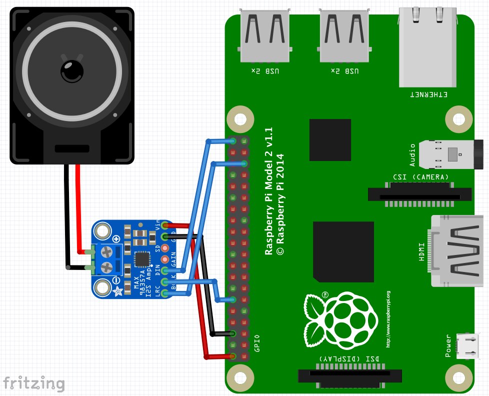
The little board costs about $6, making it a cheap and compact solution for projects like this one. The gain can be adjusted as well using the gain pin and resistors of different values, but leaving it disconnected works just as well, resulting in 9dB gain. Other possible values are 3dB, 6dB, 12dB and 15dB.


Software


I already did some reconfiguration of the audio when I added my USB microphone for voice control. Mainly to configure a different card for the default capture and playback devices. In my original tests, I was using a powered speaker connected to the stereo output jack of the Pi. Now, the Pi needs to be told to use the I2S audio rather than the stereo jack.


Before


Using "aplay -l" and "arecord -l" we can list the current playout and recording devices. The situation is as follows:


pi@piclock:~ $ aplay -l
**** List of PLAYBACK Hardware Devices ****
card 1: ALSA [bcm2835 ALSA], device 0: bcm2835 ALSA [bcm2835 ALSA]
  Subdevices: 8/8
  Subdevice #0: subdevice #0
  Subdevice #1: subdevice #1
  Subdevice #2: subdevice #2
  Subdevice #3: subdevice #3
  Subdevice #4: subdevice #4
  Subdevice #5: subdevice #5
  Subdevice #6: subdevice #6
  Subdevice #7: subdevice #7
card 1: ALSA [bcm2835 ALSA], device 1: bcm2835 ALSA [bcm2835 IEC958/HDMI]
  Subdevices: 1/1
  Subdevice #0: subdevice #0


pi@piclock:~ $ arecord -l
**** List of CAPTURE Hardware Devices ****
card 0: Device [USB PnP Sound Device], device 0: USB Audio [USB Audio]
  Subdevices: 1/1
  Subdevice #0: subdevice #0


Device Tree Overlay


A device tree is the description of the hardware in a system. And lucky for me, the device tree of the HiFiBerry DAC can be reused for this little amplifier board, making the configuration extremely easy. In the Pi's config file, the audio device tree parameter needs to be commented out and the hifiberry-dac overlay needs to be enabled.


pi@piclock:~ $ sudo nano /boot/config.txt

# Enable audio (loads snd_bcm2835)
#dtparam=audio=on
dtoverlay=hifiberry-dac


A reboot is required to apply the changes:


pi@piclock:~ $ sudo reboot


After


After the reboot, using the same commands we used before applying the device tree overlay, it is possible to see the change has successfully been applied:


pi@piclock:~ $ aplay -l
**** List of PLAYBACK Hardware Devices ****
card 1: sndrpihifiberry [snd_rpi_hifiberry_dac], device 0: HifiBerry DAC HiFi pcm5102a-hifi-0 []
  Subdevices: 1/1
  Subdevice #0: subdevice #0


pi@piclock:~ $ arecord -l
**** List of CAPTURE Hardware Devices ****
card 0: Device [USB PnP Sound Device], device 0: USB Audio [USB Audio]
  Subdevices: 1/1
  Subdevice #0: subdevice #0


The playback device has changed, the capture device hasn't. Exactly what was needed.


Test


Now, what's the best way to test the new audio config than by turning on the radio using voice control?


You don't have permission to edit metadata of this video.
Edit media
x
image
Upload Preview
image


image


Navigate to the next or previous post using the arrows.

image
  • Sign in to reply

Top Comments

  • mcb1
    mcb1 over 9 years ago +1
    Now that is clever!. I like the acknowledgement and icon, rather than just turning it on. Later you'll wish you can fit this to your children .. Mark
  • fvan
    fvan over 9 years ago in reply to mcb1 +1
    Thought it would make it more interactive than just launching the radio or whatever command is executed There is text-to-speech and an LED matrix, so why not use them, right? Later you'll wish you can…
  • clem57
    clem57 over 9 years ago +1
    How elegant a design! Clem
  • DAB
    DAB over 9 years ago

    Very nice.


    With that basic capability you could do a lot with this basic design.


    DAB

    • Cancel
    • Vote Up 0 Vote Down
    • Sign in to reply
    • More
    • Cancel
  • fvan
    fvan over 9 years ago in reply to clem57

    Thanks clem57, glad you like it!!

    • Cancel
    • Vote Up 0 Vote Down
    • Sign in to reply
    • More
    • Cancel
  • clem57
    clem57 over 9 years ago

    How elegant a design!

    Clem

    • Cancel
    • Vote Up +1 Vote Down
    • Sign in to reply
    • More
    • Cancel
  • fvan
    fvan over 9 years ago in reply to mcb1

    Thought it would make it more interactive than just launching the radio or whatever command is executed image There is text-to-speech and an LED matrix, so why not use them, right?


    Later you'll wish you can fit this to your children ..

    I already do sometimes image

    • Cancel
    • Vote Up +1 Vote Down
    • Sign in to reply
    • More
    • Cancel
  • mcb1
    mcb1 over 9 years ago

    Now that is clever!.

    I like the acknowledgement and icon, rather than just turning it on.


    Later you'll wish you can fit this to your children .. image

    Mark

    • Cancel
    • Vote Up +1 Vote Down
    • Sign in to reply
    • More
    • Cancel
element14 Community

element14 is the first online community specifically for engineers. Connect with your peers and get expert answers to your questions.

  • Members
  • Learn
  • Technologies
  • Challenges & Projects
  • Products
  • Store
  • About Us
  • Feedback & Support
  • FAQs
  • Terms of Use
  • Privacy Policy
  • Legal and Copyright Notices
  • Sitemap
  • Cookies

An Avnet Company © 2025 Premier Farnell Limited. All Rights Reserved.

Premier Farnell Ltd, registered in England and Wales (no 00876412), registered office: Farnell House, Forge Lane, Leeds LS12 2NE.

ICP 备案号 10220084.

Follow element14

  • X
  • Facebook
  • linkedin
  • YouTube