element14 Community
element14 Community
    Register Log In
  • Site
  • Search
  • Log In Register
  • Community Hub
    Community Hub
    • What's New on element14
    • Feedback and Support
    • Benefits of Membership
    • Personal Blogs
    • Members Area
    • Achievement Levels
  • Learn
    Learn
    • Ask an Expert
    • eBooks
    • element14 presents
    • Learning Center
    • Tech Spotlight
    • STEM Academy
    • Webinars, Training and Events
    • Learning Groups
  • Technologies
    Technologies
    • 3D Printing
    • FPGA
    • Industrial Automation
    • Internet of Things
    • Power & Energy
    • Sensors
    • Technology Groups
  • Challenges & Projects
    Challenges & Projects
    • Design Challenges
    • element14 presents Projects
    • Project14
    • Arduino Projects
    • Raspberry Pi Projects
    • Project Groups
  • Products
    Products
    • Arduino
    • Avnet & Tria Boards Community
    • Dev Tools
    • Manufacturers
    • Multicomp Pro
    • Product Groups
    • Raspberry Pi
    • RoadTests & Reviews
  • About Us
  • Store
    Store
    • Visit Your Store
    • Choose another store...
      • Europe
      •  Austria (German)
      •  Belgium (Dutch, French)
      •  Bulgaria (Bulgarian)
      •  Czech Republic (Czech)
      •  Denmark (Danish)
      •  Estonia (Estonian)
      •  Finland (Finnish)
      •  France (French)
      •  Germany (German)
      •  Hungary (Hungarian)
      •  Ireland
      •  Israel
      •  Italy (Italian)
      •  Latvia (Latvian)
      •  
      •  Lithuania (Lithuanian)
      •  Netherlands (Dutch)
      •  Norway (Norwegian)
      •  Poland (Polish)
      •  Portugal (Portuguese)
      •  Romania (Romanian)
      •  Russia (Russian)
      •  Slovakia (Slovak)
      •  Slovenia (Slovenian)
      •  Spain (Spanish)
      •  Sweden (Swedish)
      •  Switzerland(German, French)
      •  Turkey (Turkish)
      •  United Kingdom
      • Asia Pacific
      •  Australia
      •  China
      •  Hong Kong
      •  India
      • Japan
      •  Korea (Korean)
      •  Malaysia
      •  New Zealand
      •  Philippines
      •  Singapore
      •  Taiwan
      •  Thailand (Thai)
      • Vietnam
      • Americas
      •  Brazil (Portuguese)
      •  Canada
      •  Mexico (Spanish)
      •  United States
      Can't find the country/region you're looking for? Visit our export site or find a local distributor.
  • Translate
  • Profile
  • Settings
Pi IoT
  • Challenges & Projects
  • Design Challenges
  • Pi IoT
  • More
  • Cancel
Pi IoT
Blog PiIoT - The perfect reading place #8 [tech]: Art-a-tronic, setting the moving parts
  • Blog
  • Forum
  • Documents
  • Polls
  • Files
  • Events
  • Mentions
  • Sub-Groups
  • Tags
  • More
  • Cancel
  • New
  • Share
  • More
  • Cancel
Group Actions
  • Group RSS
  • More
  • Cancel
Engagement
  • Author Author: balearicdynamics
  • Date Created: 24 Jul 2016 10:36 AM Date Created
  • Views 620 views
  • Likes 10 likes
  • Comments 3 comments
  • psoc4
  • cad design
  • animatronic
  • piiot
  • 3D Printing
  • stepper motor
  • raspberry pi
  • gearbest
  • iot
  • piiot challenge
  • cypress
  • motor controller
  • art-a-tronic
  • mechanic design
Related
Recommended

PiIoT - The perfect reading place #8 [tech]: Art-a-tronic, setting the moving parts

balearicdynamics
balearicdynamics
24 Jul 2016

The moving parts

The Art-a-tronic animatronic (see the previous posts PiIoT - The perfect reading place #7 [tech]: Art-a-tronic, mechanic design and PiIoT - The perfect reading place #6 [tech]: Art-a-tronic, performing the new opera for details) is built with seven moving components as shown in the images below:

imageimage

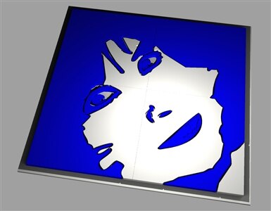
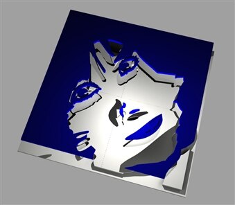
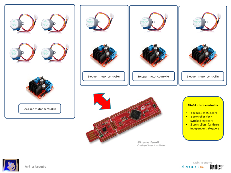
The entire 30x30 cm structure has been designed as a series of four modules to be joined together due to the plan surface limitations of the 3D printer. Thus every moving part will be controlled by a stepper motor, as shown in the scheme below.

image


Stepper motors as linear transducers

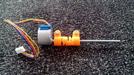
Every blue part of the animatronic will change its height when it is moved, so seven GearBest stepper motors have been used to make as many linear transducers; one for every moving part. The four synched parts uses a single controller to generate the steps. The movement is controlled by a Cypress PSoC4 micro controller acting as the main unit for the sensors (will be discussed further) and the motors.

The conversion from the rotatory movement of the steppers to the linear movement of the pats uses a very similar method to those used in the CNC machines, 3D printers and more.


The motor joint design

The threaded vertical shaft of the transducer is coaxial to the stepper axis shaft and needs a flexible joint: its role is to fix firmly the two aligned components and give a minimum of flexibility to prevent excessive mechanical stress.

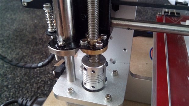
A motor joint used in many 3D printers z-axis movementimage


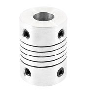
Due to the large number of joints needed for this project - the complete set of moving parts involves about 100 of them - it was worth to design a custom one with some structural changes to make it printable.

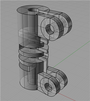
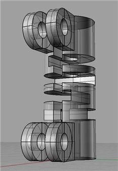
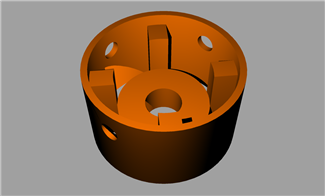
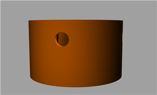
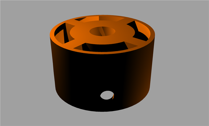
The images below show the rendered CAD model

imageimageimage

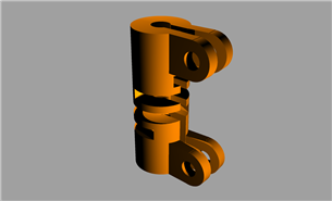
The same principle of the analog Aluminium component has been kept: robust and flexible able to lock the two coaxial components.

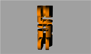
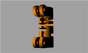
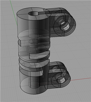
The following semitransparent images show how the internal part is designed; the stepper motor shaft has a different diameter than the M3 threaded bar used for the vertical movement.

  imageimageimage

3d printing and assembling the motor joint

Again after some 3D printing tests the joints are printed with PLA, 100% fill and supports. As these parts are small it is needed to use the raft support to keep them in place until the 3D printing finishes. The resulting g-code requires less than 30 minutes printing time.

image

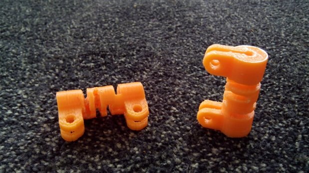
Stress tests confirmed this part as easy to assemble, robust and flexible.

imageimage

Connecting the threaded bar to the moving parts

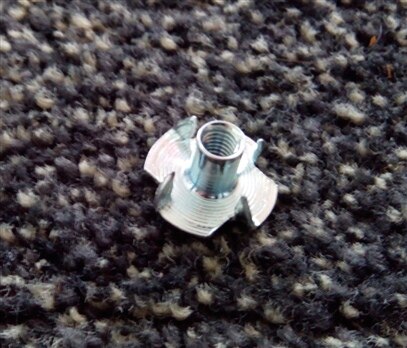
The last step to make any part moving is to connect the M3 threaded bar to the moving part. Also in this case the mechanism is very similar to the 3D printer z-axis movement, as shown in the image below.

image

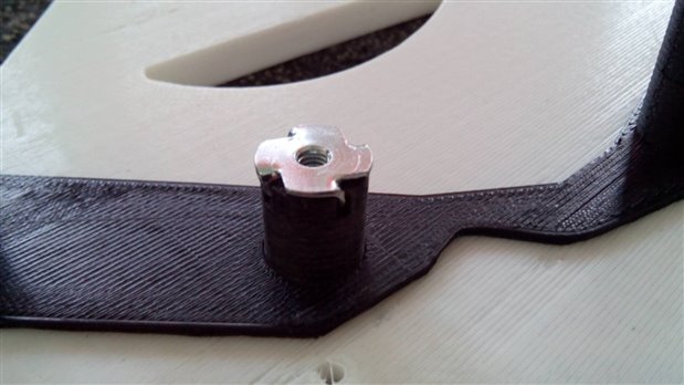
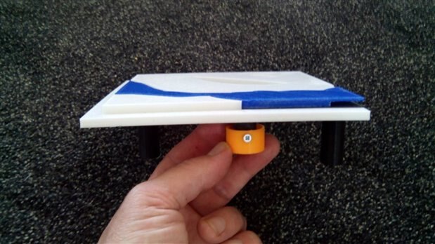
The very first tests have been done with an M3 nut, but it was not sufficient; the threaded pipe of the moving part should be longer than just a couple of mm. The image below shows the adopted component and how it fits in the threaded bar.

imageimage

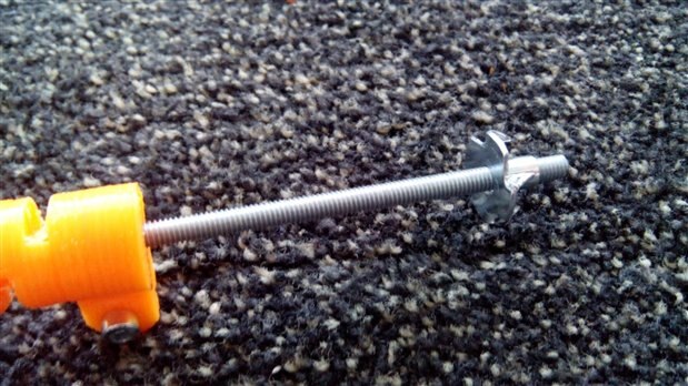
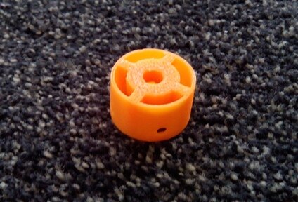
The form factor of this component makes it easy to insert to the end of the moving part axis, but a last problem arises: should be firmly locked, easy to assemble and replace on damage for easy maintenance. So a last 3D printed object has been designed: a lock cap that can be screwed to the moving pipe as shown in the images below.

imageimageimage

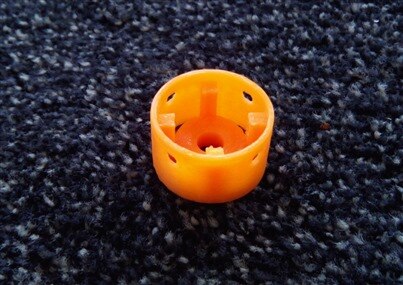
And this is the resulting 3D printed sample

imageimage

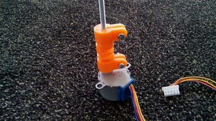
The complete movement assembly

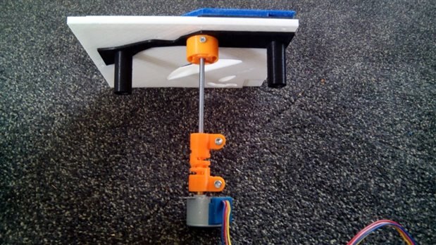
The image gallery below shows the complete movement assembly of the parts.

image

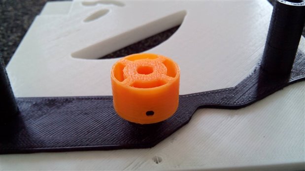
The threaded pipe set in place

image

The 3D printed cap in place

image

The 3D printed cap in place

image

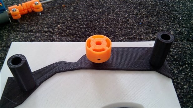
The moving part assembled with the threaded pipe to the bottom

image

The motor connected to the moving part

  • Sign in to reply

Top Comments

  • DAB
    DAB over 9 years ago +1
    Very nice post. I like the 3D printed parts for attaching longer shafts to the stepper motors. Very cool. DAB
  • balearicdynamics
    balearicdynamics over 9 years ago in reply to pettitda +1
    Hello David, the addition of injection molded parts should be excluded a-priori by the unavailability of the technology (or I have misunderstood what you mean?) and also for a construction choice. I say…
  • balearicdynamics
    balearicdynamics over 9 years ago in reply to pettitda

    Hello David,


    the addition of injection molded parts should be excluded a-priori by the unavailability of the technology (or I have misunderstood what you mean?) and also for a construction choice.


    I say, IMHO the problem is not the use of the 3D printing technology as well as an alternative choice like the creation of CNC parts. The problem is in the design; when designing mechanical moving parts it is needed to add a sort of extra dimension to the design and missing this moving dimension it is one of the most frequent mistakes I see in the 3D printed projects, also on specialised sites.

    Adopting a technology, the 3D printing in this case, first you should know the issues and the advantages to adapt the design to the  reality. Then moving parts should be designed taking care of the movement as a fourth dimension.


    About just the static aspects of the question please take a look to this link: Cardboard Chair - Danni Design (this is just one of many similar products) To the common user these solution sounds incredible, wonderful wow! A construction engineer instead is not so excited; he knows very well how the structural engineering technologies by years explored the math of these kind of approaches. The "secret" lays in the structure usage: a usually weak material can be spatially organised in a way to build extremely strong objects. The most ancient application of this approach is the egg. Its structure should be extremely robust responding to certain kind of forces and extremely fragile when different forces solicit it. Another great example is just our tibia. This bone can support a vertical load weight of several tons while it breaks with a cross shot of few kilograms. Just because it is not "engineered" for this role.


    In the case of this building I have tried to consider the mechanical aspects and where the forces act on the  system to grant the best reliability with the less use of material. Considering the motor support example - barely copied from the widely diffused Aluminium ones - I have "refactored" the concept trying to adapt to a different material and technology.

    • What is the advantage of the joint ? Supporting few degree of potential misalignment between the motor shaft and the vertical motion transducer threaded bar.
    • Is PLA sufficiently flexible ? Yes but the the horizontal cuts should be deeper and the thickness should be wider (2 mm) due to the difficult removing the support after printing.
    • Where are the most heavy forces applied ? Sounds obvious that are the rotational torsion: with a good balance between the right acceleration curve of the stepper motor when it starts and the material fill percentage torsion is very well supported.

    This and all the other factors that should be considered for a complex structure like this are essential to be considered in the design phase, avoiding a lot of experimental tests that not always grant to reach the best solution.


    Enrico


    (the image below is one of my preferite modular origami structures. You can make extremely robust polyhedric solids joining many of these base element. Just done with thin paper!)

    image

    • Cancel
    • Vote Up +1 Vote Down
    • Sign in to reply
    • More
    • Cancel
  • pettitda
    pettitda over 9 years ago

    Very interesting post.  Do you think the 3D printed parts will be robust enough to be used in a public display which gets a lot of daily use?  Or do you plan to have some injection molded parts built? 

    • Cancel
    • Vote Up 0 Vote Down
    • Sign in to reply
    • More
    • Cancel
  • DAB
    DAB over 9 years ago

    Very nice post.


    I like the 3D printed parts for attaching longer shafts to the stepper motors.


    Very cool.

    DAB

    • Cancel
    • Vote Up +1 Vote Down
    • Sign in to reply
    • More
    • Cancel
element14 Community

element14 is the first online community specifically for engineers. Connect with your peers and get expert answers to your questions.

  • Members
  • Learn
  • Technologies
  • Challenges & Projects
  • Products
  • Store
  • About Us
  • Feedback & Support
  • FAQs
  • Terms of Use
  • Privacy Policy
  • Legal and Copyright Notices
  • Sitemap
  • Cookies

An Avnet Company © 2025 Premier Farnell Limited. All Rights Reserved.

Premier Farnell Ltd, registered in England and Wales (no 00876412), registered office: Farnell House, Forge Lane, Leeds LS12 2NE.

ICP 备案号 10220084.

Follow element14

  • X
  • Facebook
  • linkedin
  • YouTube