The moving parts
The Art-a-tronic animatronic (see the previous posts PiIoT - The perfect reading place #7 [tech]: Art-a-tronic, mechanic design and PiIoT - The perfect reading place #6 [tech]: Art-a-tronic, performing the new opera for details) is built with seven moving components as shown in the images below:
The entire 30x30 cm structure has been designed as a series of four modules to be joined together due to the plan surface limitations of the 3D printer. Thus every moving part will be controlled by a stepper motor, as shown in the scheme below.
Stepper motors as linear transducers
Every blue part of the animatronic will change its height when it is moved, so seven GearBest stepper motors have been used to make as many linear transducers; one for every moving part. The four synched parts uses a single controller to generate the steps. The movement is controlled by a Cypress PSoC4 micro controller acting as the main unit for the sensors (will be discussed further) and the motors.
The conversion from the rotatory movement of the steppers to the linear movement of the pats uses a very similar method to those used in the CNC machines, 3D printers and more.
The motor joint design
The threaded vertical shaft of the transducer is coaxial to the stepper axis shaft and needs a flexible joint: its role is to fix firmly the two aligned components and give a minimum of flexibility to prevent excessive mechanical stress.
A motor joint used in many 3D printers z-axis movement
Due to the large number of joints needed for this project - the complete set of moving parts involves about 100 of them - it was worth to design a custom one with some structural changes to make it printable.
The images below show the rendered CAD model
The same principle of the analog Aluminium component has been kept: robust and flexible able to lock the two coaxial components.
The following semitransparent images show how the internal part is designed; the stepper motor shaft has a different diameter than the M3 threaded bar used for the vertical movement.
3d printing and assembling the motor joint
Again after some 3D printing tests the joints are printed with PLA, 100% fill and supports. As these parts are small it is needed to use the raft support to keep them in place until the 3D printing finishes. The resulting g-code requires less than 30 minutes printing time.
Stress tests confirmed this part as easy to assemble, robust and flexible.
Connecting the threaded bar to the moving parts
The last step to make any part moving is to connect the M3 threaded bar to the moving part. Also in this case the mechanism is very similar to the 3D printer z-axis movement, as shown in the image below.
The very first tests have been done with an M3 nut, but it was not sufficient; the threaded pipe of the moving part should be longer than just a couple of mm. The image below shows the adopted component and how it fits in the threaded bar.
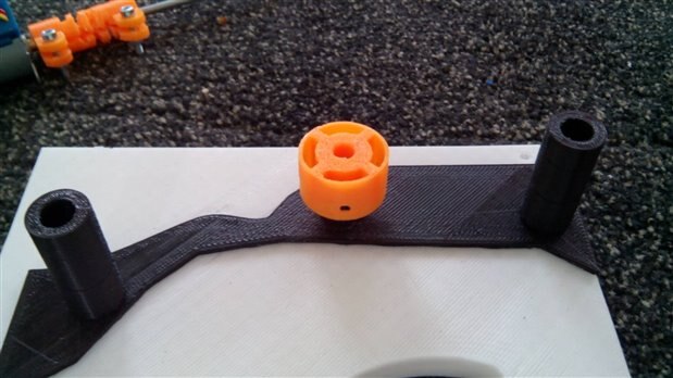
The form factor of this component makes it easy to insert to the end of the moving part axis, but a last problem arises: should be firmly locked, easy to assemble and replace on damage for easy maintenance. So a last 3D printed object has been designed: a lock cap that can be screwed to the moving pipe as shown in the images below.
And this is the resulting 3D printed sample
The complete movement assembly
The image gallery below shows the complete movement assembly of the parts.
 |
|---|
The threaded pipe set in place |
The 3D printed cap in place |
The 3D printed cap in place |
The moving part assembled with the threaded pipe to the bottom |
The motor connected to the moving part |


Top Comments
-

DAB
-
Cancel
-
Vote Up
+1
Vote Down
-
-
Sign in to reply
-
More
-
Cancel
Comment-

DAB
-
Cancel
-
Vote Up
+1
Vote Down
-
-
Sign in to reply
-
More
-
Cancel
Children