Introduction
Another piece involving LEDs. This time I chose some small SOT23 amber ones.
The Work
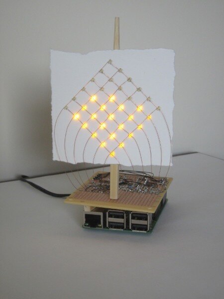
Here it is on a small table in my workroom.
The following video shows it working.
At the start I was going to have it as another canvas on the wall but, as it gradually developed, it went through
a phase where I was going to have the grid of LEDs sitting in a preservative jar, but I didn't entirely like that
either so it finally ended up as this free-standing kind of 'ship' idea. That's art for you!
The rolling flicker, that you see partway through the video, isn't apparent in real life. The matrix is scanned and
is interacting with the electronic shutter of the camera's video sensor. Unfortunately, the video also makes the
LEDs look very much brighter than they appear to the eye.
The Technical Stuff
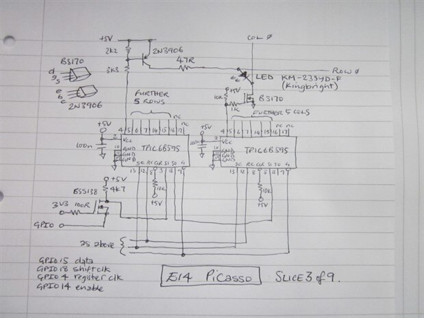
Here's the circuit diagram.
The circuit is a bit messy (too many components) and could be greatly simplified. When I started this challenge
I decided I'd try and recycle old parts I've got lying around, rather than just keep buying new stuff, but it does
mean that some of this design is getting a bit convoluted. The shift registers keep appearing because I have
several tubes of them (they were originally excess parts for products manufactured about 25 years ago that
were kept as spares and which I later rescued from going into an electrical-waste skip. I looked them up on
TI's website and, amazingly, they still make them; probably because they had an automotive use).
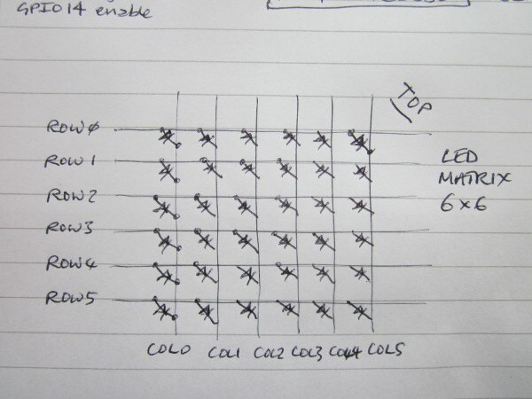
Rather than try and drive 36 LEDs using GPIO lines, the LEDs are arranged in a 6x6 matrix, with 6 columns
and 6 rows. The drivers to those rows and columns are, in turn, controlled by shift register outputs, thus
reducing the GPIO count to four. I'm going to have a 1:6 multiplex on the columns and present the data on
the rows. When I experimented with a single LED I found I needed about 10mA to get the illumination I wanted
for a reasonable 'dot' on the paper. That means the row drive will need to work at something like 60mA
[in order to average 10mA] and the column drive will need to cope with up to 360mA [if all 6 LEDs are on].
Because I didn't have a good option handy for driving the 360mA if I put it on the high side, and the shift
register isn't quite rated for doing it if I did it on the low side, I decided to put BS170 MOSFETs on the low
side for the 360mA and 2N3906 transistors on the high side for the row drive since I have plenty of both.
For the level-conversion up from the Pi's 3.3V GPIO pins to the shift register 5V CMOS inputs, this time
around I experimented with using BSS138 MOSFETs in a common-gate configuration (similar to a
cascode-type arrangement) where the MOSFET shields the Pi from the 5V. The BSS138 parts are in a
surface-mount SOT23 package but they're very easy to work with and there's no problem soldering them
with an ordinary soldering iron. [Although it worked adequately for the piece, the output waveforms aren't
ideal. They stall momentarily around the 3V point.]
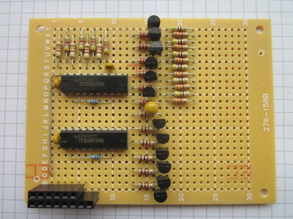
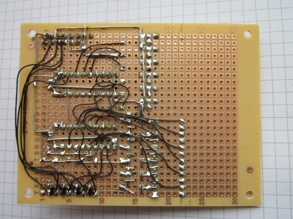
Here's the interface board as I've built it on a small prototyping board with the wiring done with wire-wrap
wire soldered to the pads.
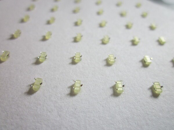
For the display part, I super-glued the LEDs down to a piece of fairly heavy cartridge paper. They actually
face down towards the paper, so the pixel is formed by the light that gets reflected back up through the
body and what spills out the sides. Visually, it was much more comfortable to look at than having the very
bright dot of light from the die directly visible.
Here they are, glued to the paper, before the wiring was done.
The paper was then glued to part of a chop-stick, which acts as the mast, and strands of wire from a stranded
cable were used to wire the matrix to the drive parts on the circuit board.
The Code
Once I had the hardware built and working, I needed to come up with some code. Again I've used Python. That
probably isn't a particularly good decision, given that it needs reasonably accurate timing, but I'm really pushed
for time here and so this is the point where 'good design' flies out the window and 'whatever works' is now the
order of the day. In practice it worked surprisingly well, with the only noticeable blemishes coming when the Pi
starts doing network stuff (whenever the network connector LED flashes, the display stutters).
Here's the code. I won't go through it in detail - hopefully it's fairly understandable. Getting the right LEDs to light
up, when I wanted them to, took a few iterations of the code but it's very easy to debug something when you can
literally see the results of what you're doing displayed in front of you.
# Trickle-Down (slice3.py)
import time
import RPi.GPIO as GPIO
import random
# set GPIO direction for pins we are using to output
GPIO.setmode(GPIO.BCM)
GPIO.setup(18,GPIO.OUT) #clock
GPIO.setup(4,GPIO.OUT) #latch
GPIO.setup(15,GPIO.OUT) #data
GPIO.setup(14,GPIO.OUT) #enable
# set them to appropriate start levels
GPIO.output(18,False)
GPIO.output(4,False)
GPIO.output(15,False)
GPIO.output(14,True)
# set up the frame store
displayStore = [[True,False,False,False,False,False,True,True],
[False,False,False,False,False,False,True,True],
[False,False,False,False,False,False,True,True],
[False,False,False,False,False,False,True,True],
[False,False,False,False,False,False,True,True],
[False,False,False,False,False,False,True,True],
[True,True,True,True,True,True,True,True,True],
[True,True,True,True,True,True,True,True,True]]
# start off with something sensible and in range in variables
fillFrame = True
currentRow = 0
currentCol = 0
nextRow = 0
nextCol = 0
displayCol = 5
frameCount = 0
floodCount = 0
testCount = 0
def outputToShiftRegisters(displayStore,displayCol):
  #two more dummy bits
  GPIO.output(18,True) # shift clock high
  GPIO.output(18,False) # shift clock low
  GPIO.output(18,True) # shift clock high
  GPIO.output(18,False) # shift clock low
  #then the column data
  for x in range(0,6): # do for the 6 bits of col data
    if x == displayCol: #set up data
      GPIO.output(15,True)
    else:
      GPIO.output(15,False)
    GPIO.output(18,True) # shift clock high
    GPIO.output(18,False) # shift clock low
  #two dummy bits
  GPIO.output(18,True) # shift clock high
  GPIO.output(18,False) # shift clock low
  GPIO.output(18,True) # shift clock high
  GPIO.output(18,False) # shift clock low
  #then the row data
  for x in range(0,6): # do for the 6 bits of row data
    if displayStore[5-x][displayCol] == False:
      GPIO.output(15,True)
    else:
      GPIO.output(15,False)
    GPIO.output(18,True) # shift clock high
    GPIO.output(18,False) # shift clock low
  #disable output drive, latch outputs, then re-enable
  GPIO.output(14,True) #enable low (s/r outputs off)
  GPIO.output(4,True) # register clock high
  GPIO.output(4,False) # register clock low
  GPIO.output(14,False) #enable high (s/r outputs back on)
  return
# main loop of the program
while testCount < 100000:
  #wait for 2ms (gives 83Hz refresh on LEDs)
  time.sleep(0.002)
  #update column count
  displayCol = displayCol + 1
  if displayCol > 5:
    displayCol = 0
    #ready to draw next frame?
    if frameCount > 39:
      frameCount = 0
      if fillFrame == True: # True, so state is trickling down
        displayStore[currentRow][currentCol] = False
        if (displayStore[currentRow + 1][currentCol] == False) and (displayStore[currentRow][currentCol + 1] == False):
          if (random.randint(0,100) > 50):
            currentRow = currentRow + 1
          else:
            currentCol = currentCol + 1
        else:
          if (displayStore[currentRow + 1][currentCol] == False) and (displayStore[currentRow][currentCol + 1] == True):
            currentRow = currentRow + 1
          else:
            if (displayStore[currentRow + 1][currentCol] == True) and (displayStore[currentRow][currentCol + 1] == False):
              currentCol = currentCol + 1
            else:
              if (displayStore[currentRow][currentCol + 1] == True) and (displayStore[currentRow + 1][currentCol] == True):
                displayStore[currentRow][currentCol] = True
                if (currentRow == 0) and (currentCol == 0):
                  fillFrame = False
                  floodCount = 6
                else:
                  currentCol = 0
                  currentRow = 0
        displayStore[currentRow][currentCol] = True
      else: # False, so state is flooding up
        floodCount = floodCount - 1
        if floodCount >= 0:
          for row in range(0,6): # do for 6 rows
            for col in range(0,6): # and 6 columns
              if ((col > floodCount) or (row > floodCount)):
                displayStore[row][col] = False
              else:
                displayStore[row][col] = True
        else:
          displayStore[0][0] = True
          fillFrame = True
          currentCol = 0
          currentRow = 0
    else:
      frameCount = frameCount + 1
  outputToShiftRegisters(displayStore,displayCol)
  testCount = testCount + 1
GPIO.cleanup()
Links to the previous slices:
9 Pieces of Pi: Slice 1: The Long Way Round
9 Pieces of Pi: Slice 2: Manifesto for Art Electronic
If you are interested in my other blogging here on Element14, this link takes you to an index page where many of them are listed: jc2048 Blog Index
I'm following along with this Design Challenge as an independent participant, not as one of the challengers. I'm not entering the competition for the prizes.

Top Comments
-

DAB
-
Cancel
-
Vote Up
+1
Vote Down
-
-
Sign in to reply
-
More
-
Cancel
Comment-

DAB
-
Cancel
-
Vote Up
+1
Vote Down
-
-
Sign in to reply
-
More
-
Cancel
Children