


Goal: Super-de-dooper range hood. My range hood will be smarter than your range hood  (i.e. a smart, connected appliance above the stove to remove fumes, take images of dinner for my wife to summon me, and do other cool things too!) See Blog Post #1 for links to the complete build process. All Eagle files, board, schematic, gerber files are on my Github here.
Last week completed the sheet metal work. If you haven't been following the entire build, this involved a custom design of sheet metal done in Autodesk Inventor. The metal was designed to suit my awkward 40" opening. The plans were sent to to a local fabrication house for manufacturing. I received the components last week and did a "guts swap" from a donor hood, and installed the new hood in my kitchen. Using the donor hood control panel, I have validated that everything powers up and runs and fits within the new shell.
Before that, I completed about 80-90% of the control algorithm. I used a breadboard to hold all the components and validate communications and control over the different items. I am using four sensors to detect Methane, Propane, Hydrogen, and CO gasses and also a temperature/humidity sensor. Using NodeRed, I was able to talk to all the different hardware components (except the touchscreen which was not able to plug in with the breadboard / PiCobbler kit). I have wifi connectivity, MQTT communications, auto and manual control, and the ability to take images with both the Raspberry Pi Camera and the GridEye camera. I haven't talked much about the cameras but that will be ready shortly...
PCB Design

One thing I really want to start incorporating into a lot of my projects is better circuit boards. I've spent loads of time using breadboards, soldered plenty of perfboards, and recently even started doing wire wrapping (Thanks Ben!); but the end result is generally pretty rough looking. So I downloaded a copy of Eagle back in January and got playing around. I've used Fritzing leading up to this, but it is very clunky in my experience. Eagle is a professional schematic and PCB program used by many people. I recently watched a YouTube video about someone (maybe Dave Jones?) who looks at loads of different people's boards and he can tell right away if the board was done in Fritzing or not... and that was not meant as a compliment to the PDB designer. At any rate, I jumped right in and started figuring things out. This is a professional, high-grade piece of software, so it may be more difficult to pick up straight away without some training or tutorials.
One limitation of the free version of Eagle is that the PCB design is limited to smaller board sizes. In my case, the PCB I needed was only slightly larger than a Raspberry Pi, so this was not an issue.

I ended up by making two different boards - one as the main "hat" and one to hold the air quality sensors. Since one is not much more than a mechanical mount, it was very straight forward. The other has to hold loads of components and serve many functions so took a lot more time. In reality, the "range hood" board (the main one) was designed first and probably took about 20-30+ hours to design; from schematic to ordering. The air quality sensor board was done second, and took one morning, and I threw in a few extras while I was at it.
I /just now/ read this post from jschools which talks in detail about the process of creating a PCB from EAGLE - it is a good read and while worth the time.
In general, there are at least two steps for making a PCB
- Create a schematic
- Create the PCB layout and send to fabricator or "roll your own"
Of course there is a lot which goes in to each one; but these are the high level steps. Creating the schematic consists of "adding" your components to the work area, then linking them all up with what are called "nets". A user can drag & drop components around the work area and if things are done correctly, this can make a very nice, clean & professional looking schematic. If for nothing else, this is the best form of documentation. I have loads and loads of notepads, scrap paper, 'backs of envelops',, fritzing documents and whatnotery floating around for all my other projects to hold the needed information.
The second step is to make the circuit board. Each part in Eagle has two different components - a "symbol" and a "package". If we take a resistor, for example, the symbol is essentially always the same - the familiar zigzag line. The Package however varies wildly from one type to another. This is one place that Eagle differs from other packages like Fritzing. It is not easy to just grab some generic 220 Ohm resistor without first knowing if it is a through-hole, an 0805 surface mount, a power resistor, or some other form factor. One must first sift through loads of different possibilities before being able to get the correct 'package' to place on the schematic. The parts library has a decent search capability, and google has an even better one, so finding the correct components usually doesn't take too long. One can even create their own custom library to add anything they like. I would like to go down this path at some point but this project was OK with the readily available ones.
The benefit of this complicated component selection, is that when it comes to doing the PCB, then the correct footprint, drill holes, and silkscreen symbols will be placed accordingly. One can simply hit "create PCB" and start dragging and dropping the components with the already correct size & shape.
So James - What did you make this week?
Without further adieu, here is the "final" schematic for the two different boards. Full Eagle package including Gerber files are available on GitHub. I will go through the individual components in more details below, then the video also has information. This should cover what will likely be the final, complete schematic for this project.
Logic level converter:
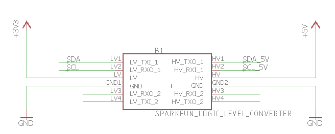
It is really just a board with some transistors on it. This particular one is marketed as bi-directional and I2C compatible. This will be sitting in between the RPi and the analog to digital converter. The ADC will be running at 5VDC since the MQ sensors require that voltage to work properly. The Bi-Directional-ability of this board is required since I2C uses a single wire for RX/TX and either the master or the slave component can be driving the line level high or low. The clock is generally always driven by the controller.
Analog to digital:
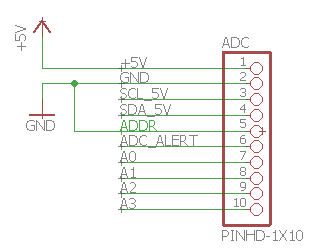
The ADC is pretty straight forward - it runs on 5V and of course a ground connection. I need to connect it to the 5V I2C clock and data lines. Pin, #5 sets the I2C address. In my case I tie the address to ground. This gives the address of 0x48 on the I2C bus.
I could choose from any of the following options, which would be useful if I needed to expand the number of ADC channels -
0x48 - GND
0x49 - VDD
0x4A - SDA
0x4B - SCL
GridEye connector
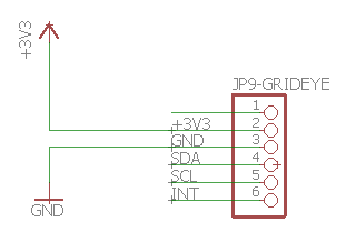
I added a jumper for the GridEye camera. This runs on the 3.3v I2C bus and uses 0x69 as the address. Pin 1 is a VIN pin which could be used to supply 5 volts to this particular breakout board. In my case I leave it unhooked and run 3.3v in pin #2. Pin #6 is a configurable interrupt pin. I could chose some setpoint for each of the individual 64 pixels; and when this temperature is exceeded the GridEye will assert this pin to alert the controller.
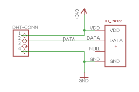
DHT22
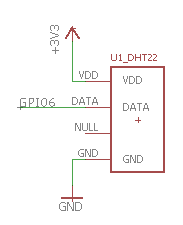
The DHT sensor just needs power (3.3), Ground, and a GPIO pin to work. In my case I am using GPIO #6 for the data line. The RaspberryPi has a library running in Node red to request a reading from the DHT by pulsing the data line; then the DHT responds on the same data line with temperature and humidity. This schematic component is technically wrong since it shows the sensor itself and not a pin header which I plan to use. Since the sensor has the same pin spacing as a pin header, this will not be a problem.
Relay board
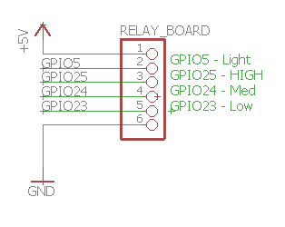
This header is designed to bring out all the required connections to go to the 4-channel realy board. It needs 5V to run the relay coils, four signal wires, plus a ground.
MQ sensor header
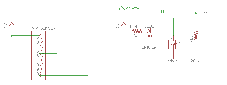
The four MQ sensors have the same basic layout. The heater and the analog pins are all run through a main header. The header brings power over on two pins; then returns the switchable ground for the heater and the analog feedback wire. In this example, I run the MQ6 / Hydrogen sensor back into pin A1 of the ADC and I'm using GPIO19 to run the MOSFET to switch the heater.
Buzzer / Fan
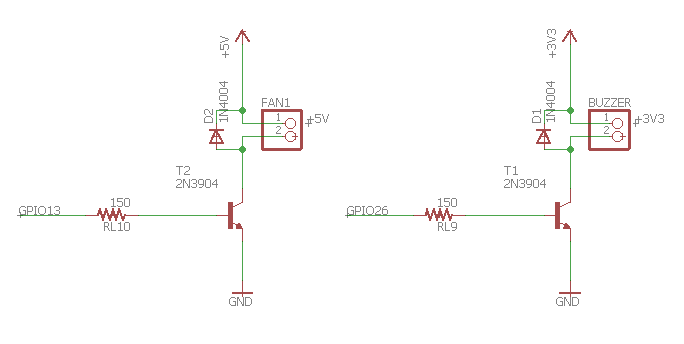
The buzzer and the fan have a basic circuit using a 2n3904 general purpose transistor as a switch. I can use a GPIO pin pushing minimal current to turn on or off 5V and 3.3v devices. I have included a flyback diode with a generic 1N4004. I haven't mentioned a fan before, but it will be used to pull air across the MQ/DHT sensor board. I'll run it with PWM.
Two headers
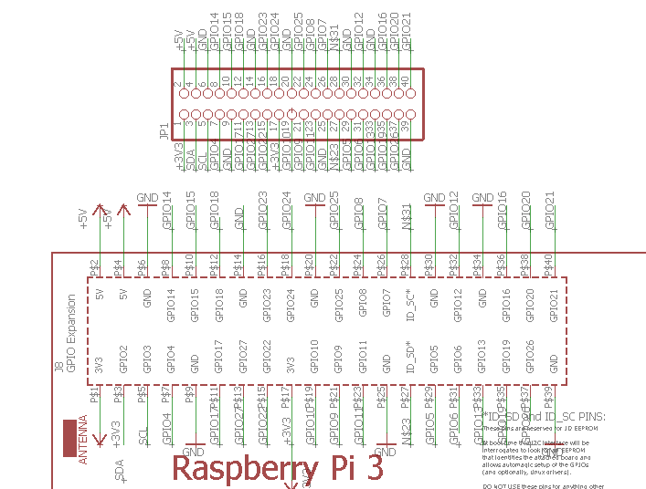
The Raspberry Pi will have its own header, plus I added a second identical one which will sit next to it. I may use this PCB in the future and this will duplicate the entire header. For the schematic, I just used a 40 pin, 2 x 20 generic pin header with 0.1" spacing.
Expansion and proto area
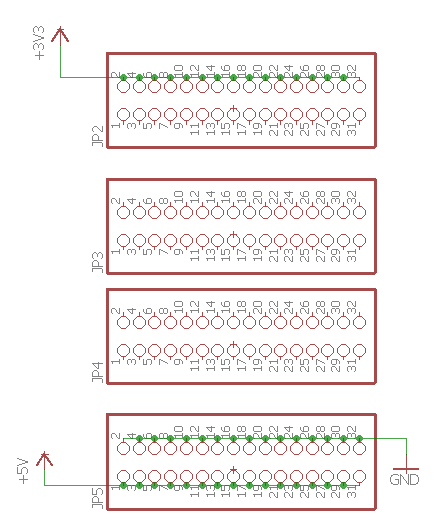
I added four more 32 pin headers (2 x 16) to serve as a prototype area. I brought out 3.3v, 5v, and ground to a few rows. Now with the secondary RPi header, plus this proto area I would have a lot of flexibility in the future to do modify and add things to this system. Scope creep anyone???
Air Quality sensor schematic
The schematic parts below describe the second PCB that I have created for this project. This board functions to hold the four MQ sensors and the DHT sensor.
MQ sensor main header

Here I have the other end of the header described above. I take in the 5V on two pins, have to return lines for the ground of the heaters, and four analog return lines going back to the main board.
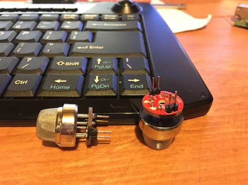
MQ individual headers

Each MQ sensor has four pins that come down from the Sparkfun breakout board that I'm using. This board made breadboarding possible, and I was able to draw the schematic and PCB without having to worry about odd "6-around" pin header on the actual sensor. If the range hood product was developed further, this component would be eliminated.
DHT header/sesnor
As noted above, the DHT sensor will be physically located out on the MQ sensor board with a cable running to it from the hat. This portion of the schematic shows the correct 4-pin header and the sensor itself. Pin 3 is not used on the DHT sensor. When I make the cable, I will only use three conductors.
PCB Design
There are probably hundreds of books out about this subject but I am, by all accounts, a greenhorn. These two PCBs are the very first that I've made. Most companies that do electrical engineering have at least one person whose main job is to lay out the PCB. Things like trace width, proper use of ground planes, proximity to noise like PWM, clk and data lines influencing high frequency analog signals can all cause problems if not taken into account. To my benefit, these two boards are probably about as simple as it gets with essentially a bunch of through hole mounting for breakout boards.
I do happen to have a very close family relation to someone who do electrical engineering & PCB layout for a rather well know auto manufacturer. I spent some time talking with them about my boards and they gave me the following advice -
- 8 mil trace width for most logic level should be sufficient. More power requires wider traces. I used 8 for most the data lines, then 16 for some and 32 for some others even though I'm sure I didn't need to go that wide.
- Don't use the auto-router! I'm sure this is controversial, and I'm sure that many-an-intern has been tasked with improving the autorouter functionality. I didn't end up trying it. I've heard that PCB layout is 90% component placement and 10% routing. If a board is efficiently laid out, then the wire routes can be much easier to make. Hand routing allows for generally better looking PCBs and more thoughtful designs to avoid issues.
There were a few other things relating to "V" shaped traces which could be problematic with <10 mil traces. Most my traces with "V" shapes are 32 mil so the copper etch is not likely to erode the traces in any detrimental manner. I could also likely use some bulk storage capacitors and am planning to add an additional ceramic cap for one of the heaters to PWM a specific voltage if time allows. Apparently even ground planes can cause problems if done wrong - if they are all "chunked" up; then they won't have the same ground potential since different sections will funnel through different width passages. In certain cases, one may be farther ahead to just manually route ground traces as needed around the board. For my purposes I think I'll be OK with the generic ground plane as shown.
Where to order?
I used a service called "JLC PCB" (jlcpcb.com) which I found through advertisements on the "Great Scott" youtube channel. They charged an insanely low $2.00 to make 10 prototype PCBs. Shipping was $18, so total price was $20 for 10 copies of the board. I got two boards (10 copies of each), so I'm $40 in. If I had ordered them at the same time I could have saved on shipping. They also air freight the boards. Since they are small and don't weigh anything, I can get them delivered from Shenzhen to Milwaukee in just a few days -
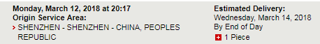
Their website takes in the Gerber files (which is another 30 volumes of textbooks); generates a preview, then allows you to submit them for final order. They then show a graph on where in production they are, for those like me who are impatient.

To generate my gerber files, I used a profile from SparkFun. Since a PCB can be thought of a several stacked layers, along with some through holes, the gerber files are defining what go into each layer. I did catch at the last second that some of my silkscreen wasn't present when I previewed the board on JLCPCB.com and had to add one more selection to the silkscreen layer.
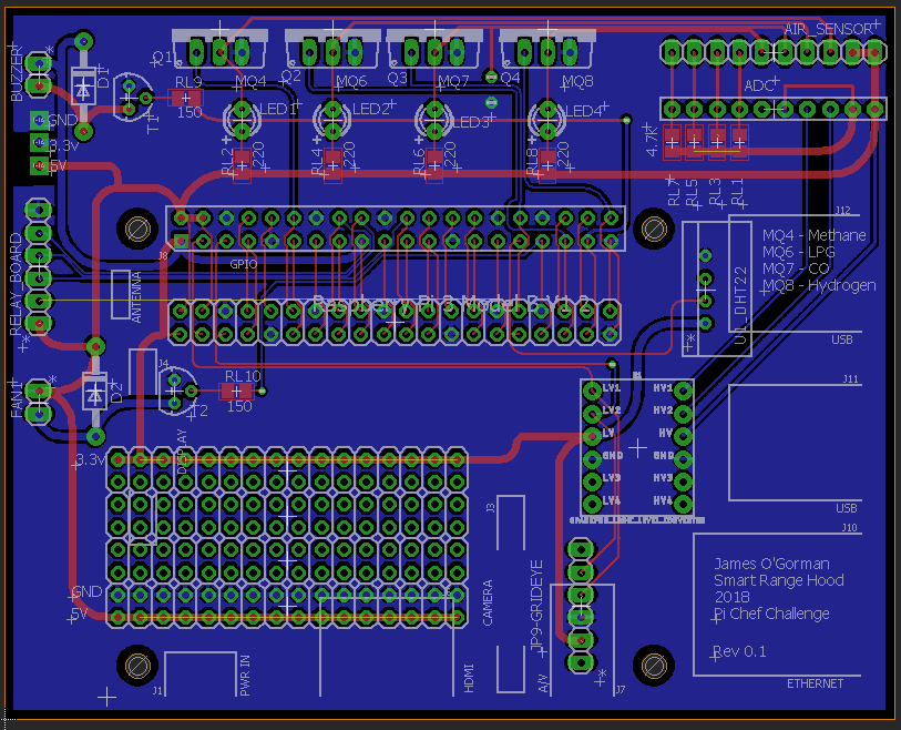
Here is the first spin of the board.
The MOSFETs are lined up along the top; with the Air sensor breakout connection in the top right. The ADC header is located just below that.
Down the left side of the board are the buzzer circuitry, some test points for GND, 3.3V, and 5V; then the header for the relay board. Below that is the connection for the fan. The large area in the bottom left is the proto area generated with a bunch of pin header components. To the right of that are the GridEye pin header and the logic level converter. The DHT pin header is visible to the right of the Raspberry Pi header and the duplicated header.
There are also drill holes indicated in this drawing.
This is the MQ sensor board on the left and some "bonus" GridEye boards on the right; which I found here. These will be cut off in post-production. And if anyone wants one, cover shipping and they are free. I get three essentially "free" on each of the 10 boards that I ordered for a total of $20... If time allows, i'll swap out the 20-80C version for the -20 to 100C version which I have ordered from Newark. This should be a direct replacement in my system once mounted on the board.

The MQ board takes in the pin header and runs the four MQ sensors and also takes the DHT22 pin header and connects to the sensor.
Iteration
I did print some versions of the boards on to copy paper to validate fitment. This is a great sanity check and was very useful for the MQ sensors. I found that the original design wasn't the best. The second design looked much better for a few reasons. I just kicked out the designs to the printed, printed with NO scaling (100%) then placed my components around the printout; pushing the pins through the paper as required. I've seen a few cases where a devices "package" was to completely accurate and the final board places them too close together than they can physically fit.
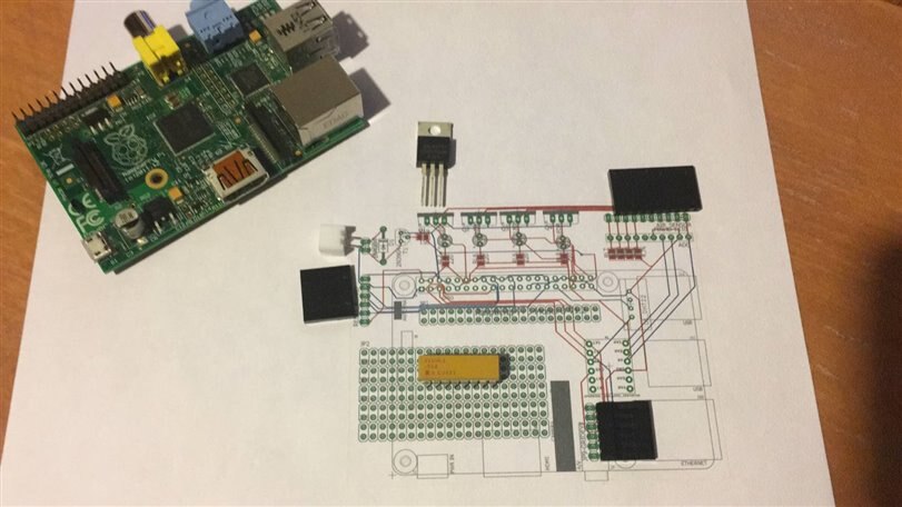
For the main PCB, there were only a few components I was curious about fitment issues. If I have to do any changes on this board, I will eliminate the portion which overhangs the USB and ethernet ports. For now, I think I'll be OK with the tall stacking header and tall stand-offs.
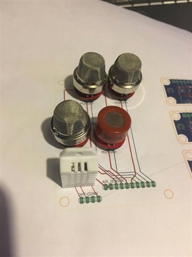
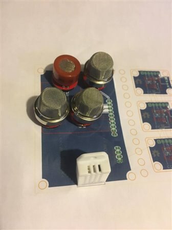
On the left is my first try at the MQ board. The sensors physically fit but I wanted to have more distance between the DHT and the MQ's since the MQ's generate a lot of heat. Second try on the right. I now have a larger gap, the DHT is front and center, and I have moved the pin headers to the side of the board which will help later with installation.
What's next???
The new human and I have been working hard on the implementation of the air sensor board. I badly need to get the RPI, cameras, and sensors installed into the new sheet metal, and this will be the last major component to do that.
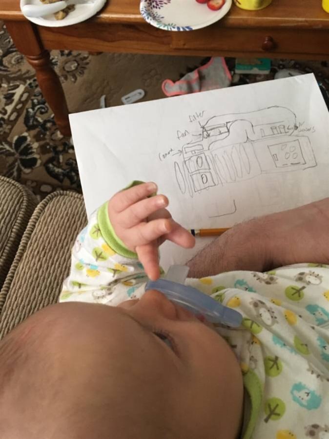
Below is more detail of that drawing. The image shows a side view and a top view of the setup. This flow channel will allow particulate-free and junk-free free air to be drawn past the sensors. This will be housed inside the hood where it can draw air in from the slots and give the cameras a view down of the stove.
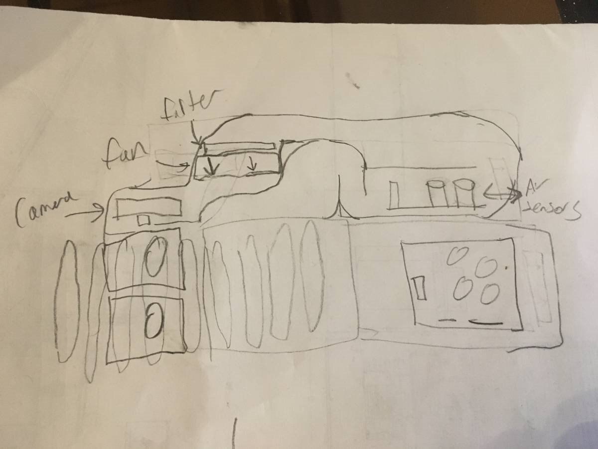
I'll use a mesh filter at the inlet (not shown), run the air around two baffles then across the air sensors. The air will then turn and be drawn back to the left by the fan. It will pass a charcoal filter then exhaust out through the front viewing area of the cameras. Because this will create positive pressure in front of the cameras, it should help prevent condensation and other junk from getting on the lenses. It will also keep a fresh flow of air going by the MQ sensors. This will be 3D printed in two halves while I wait for the PCBs to arrive. Also in the plan while I wait is getting the touchscreen back into operation. This will also ensure that any heat from the lighting won't influence the DHT or MQ sensors.
Finally - here is a very quick video of the PCB layout.
What do you guys think? Is my PCB design OK? How is the project going? Do I need to just get the project running or continue with the baffle design?
- James
Top Comments
-

genebren
-
Cancel
-
Vote Up
0
Vote Down
-
-
Sign in to reply
-
More
-
Cancel
Comment-

genebren
-
Cancel
-
Vote Up
0
Vote Down
-
-
Sign in to reply
-
More
-
Cancel
Children