element14 Community
element14 Community
    Register Log In
  • Site
  • Search
  • Log In Register
  • About Us
  • Community Hub
    Community Hub
    • What's New on element14
    • Feedback and Support
    • Benefits of Membership
    • Personal Blogs
    • Members Area
    • Achievement Levels
  • Learn
    Learn
    • Ask an Expert
    • eBooks
    • element14 presents
    • Learning Center
    • Tech Spotlight
    • STEM Academy
    • Webinars, Training and Events
    • Learning Groups
  • Technologies
    Technologies
    • 3D Printing
    • FPGA
    • Industrial Automation
    • Internet of Things
    • Power & Energy
    • Sensors
    • Technology Groups
  • Challenges & Projects
    Challenges & Projects
    • Design Challenges
    • element14 presents Projects
    • Project14
    • Arduino Projects
    • Raspberry Pi Projects
    • Project Groups
  • Products
    Products
    • Arduino
    • Avnet Boards Community
    • Dev Tools
    • Manufacturers
    • Multicomp Pro
    • Product Groups
    • Raspberry Pi
    • RoadTests & Reviews
  • Store
    Store
    • Visit Your Store
    • Choose another store...
      • Europe
      •  Austria (German)
      •  Belgium (Dutch, French)
      •  Bulgaria (Bulgarian)
      •  Czech Republic (Czech)
      •  Denmark (Danish)
      •  Estonia (Estonian)
      •  Finland (Finnish)
      •  France (French)
      •  Germany (German)
      •  Hungary (Hungarian)
      •  Ireland
      •  Israel
      •  Italy (Italian)
      •  Latvia (Latvian)
      •  
      •  Lithuania (Lithuanian)
      •  Netherlands (Dutch)
      •  Norway (Norwegian)
      •  Poland (Polish)
      •  Portugal (Portuguese)
      •  Romania (Romanian)
      •  Russia (Russian)
      •  Slovakia (Slovak)
      •  Slovenia (Slovenian)
      •  Spain (Spanish)
      •  Sweden (Swedish)
      •  Switzerland(German, French)
      •  Turkey (Turkish)
      •  United Kingdom
      • Asia Pacific
      •  Australia
      •  China
      •  Hong Kong
      •  India
      •  Korea (Korean)
      •  Malaysia
      •  New Zealand
      •  Philippines
      •  Singapore
      •  Taiwan
      •  Thailand (Thai)
      • Americas
      •  Brazil (Portuguese)
      •  Canada
      •  Mexico (Spanish)
      •  United States
      Can't find the country/region you're looking for? Visit our export site or find a local distributor.
  • Translate
  • Profile
  • Settings
Experimenting with Polymer Capacitors
  • Challenges & Projects
  • Design Challenges
  • Experimenting with Polymer Capacitors
  • More
  • Cancel
Experimenting with Polymer Capacitors
Blog Deep Dive into ESR, Introduction
  • Blog
  • Forum
  • Documents
  • Polls
  • Files
  • Mentions
  • Sub-Groups
  • Tags
  • More
  • Cancel
  • New
  • Share
  • More
  • Cancel
Group Actions
  • Group RSS
  • More
  • Cancel
Engagement
  • Author Author: fmilburn
  • Date Created: 8 May 2019 5:06 AM Date Created
  • Views 5124 views
  • Likes 12 likes
  • Comments 31 comments
  • polymer capacitor
  • tenma 72-1020
  • capacitance measurement
  • esr measurement*
  • esr
  • peak esr70
  • ad9850
  • capacitance
  • msp-exp430fr6989
Related
Recommended

Deep Dive into ESR, Introduction

fmilburn
fmilburn
8 May 2019

The element14 Experimenting with Polymer Capacitors Challenge is an opportunity to “experiment, test, breadboard, or just play around with Polymer Capacitors” and then show what was learned.  I am grateful to be one of the competitors selected to receive a Polymer Capacitor Kit for my proposal “Deep Dive into ESR”.  Polymer capacitors offer low Equivalent Series Resistance (ESR) and high capacitance in small packages.  Experiments have been carried out which measure ESR and capacitance over a range of values.  A method for measuring ESR using an oscilloscope is presented in addition to use of the Peak ESR70 meter provided in the kit.  Finally, a Panasonic polymer capacitor from the element14 kit is used to reduce ripple from a buck converter.

image


In this first post the experiment will be described and the theory behind it explained.  In the next two posts the actual experiments, results and findings will be presented.


Introduction


Equivalent Series Resistance (ESR) and the actual capacitance of capacitors are among the most important parameters for capacitor performance in a circuit.  While an ideal capacitor has no series resistance, ESR exists in all real world capacitors, albeit with very small values in some of the polymer capacitors investigated here.  There are other deviations from ideal behavior such as series inductance, parallel resistance, and memory effects (dielectric absorbtion) which we will not be addressing.


Capacitor ESR not only influences circuit behavior when new, but can worsen over time due to age (e.g. drying out of electrolyte in some capacitors), abuse, and overheating. This increases power dissipation which can start a vicious circle of continued performance reduction.  Thus, the ability to measure both capacitance and ESR quickly with an instrument like the Peak ESR70 is of value.  There is an element14 Cool Tools review of the ESR70 by Michael Wylie here.


An oscilloscope can also be used to measure ESR and provides a visual means of assessing the capacitor.  The Peak ESR70 will be used to assess how well the oscilloscope method works.


While the Peak ESR70 can be used with the circuit intact in some cases, there are limitations and it isn’t always appropriate.  The experiments performed here will be done on new capacitors outside of a circuit.  ESR is typically quoted by manufacturers at around 100 kHz which is where the Peak ESR70 operates, and also what will be used in the oscilloscope method. The reason for this will be explained shortly.


The element14 Kit


The Panasonic polymer capacitors in the element14 kit came nicely packaged in their own compartmentalized box.  They are all surface mount.  It is nice to have the assortment as it gives a good idea of the size and range of what is available.


My first impression of the Atlas Peak ESR70 is good.  It seems well made and is easy to use.

image


Objectives


The experiment seeks to understand ESR and how it differs among different polymer capacitors and from aluminum electrolytic and ceramic capacitors.  Application of polymer capacitors will be explored.  To do this we will:


  • Describe ESR and how it can be measured
  • Obtain experimental ESR value for various capacitor types and values
  • Obtain experimental capacitance values for various capacitor types and values
  • Compare and summarize findings
  • Evaluate application of polymer capacitors to reduce switching ripple in a DC-DC buck converter


Capacitance and ESR will each be measured with two different instruments / methods.  The DC-DC buck converter will be a TI SWIFTTm Power Module.


Equipment and Materials
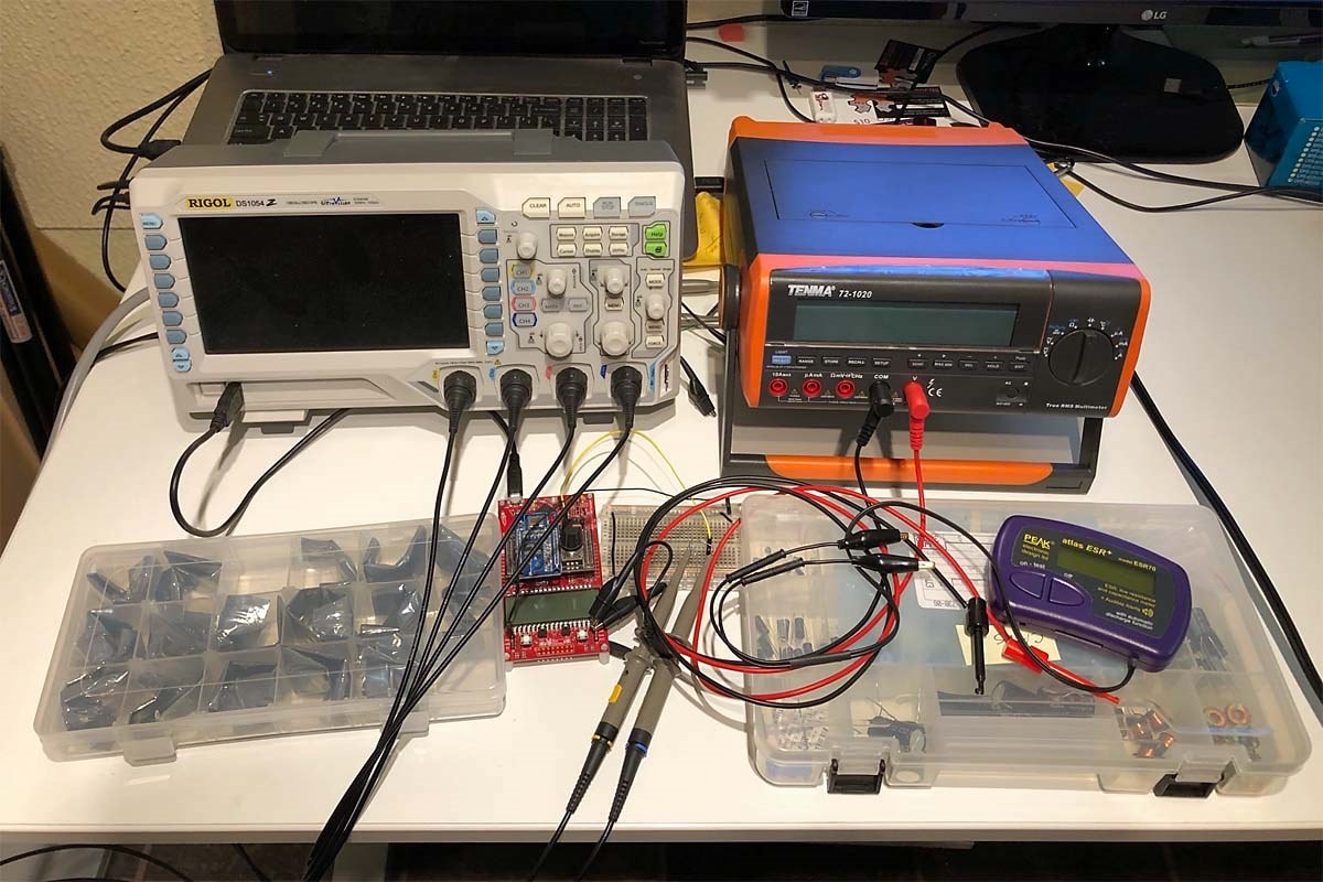
image


Equipment

  • Peak ESR70 ESR meter
  • Tenma 72-1020 40,000 count bench multimeter
  • 100 MHz oscilloscope
  • TI MSP430FR6989 Dev BoardAD9850 DDS Synthesizer


Materials

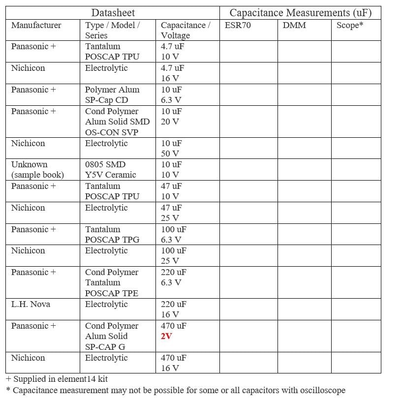
  • Panasonic polymer capacitors to be evaluated as listed in the report format section of this post.


Similarly rated (capacitance and voltage) aluminum electrolytic and ceramic capacitors readily at hand were also tested.


ESR Measurement Theory


The method for measuring ESR with an oscilloscope is shown in the following diagram:

image

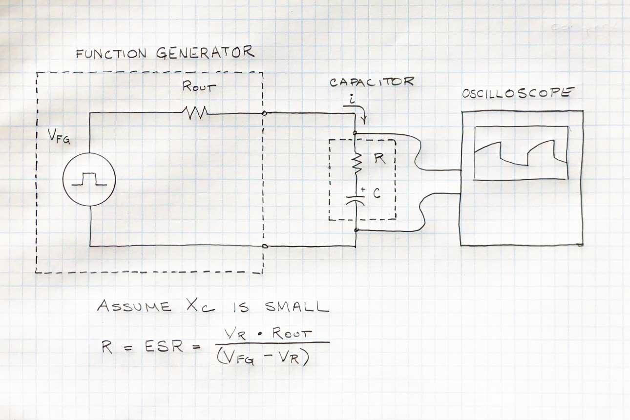
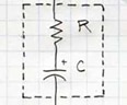
The square wave generator is modeled as an ideal square wave with a resistor Rout in series.  The capacitor is modeled as an ideal capacitor with a resistor R in series.  Voltage is measured with an oscilloscope.


In summary, if the frequency of the square wave is in the 100 kHz range an ideal capacitor begins to approximate a short circuit for the values of capacitance we are interested in.  However, a real capacitor has some equivalent series resistance (ESR) that will cause a voltage drop across the capacitor which can be observed with an oscilloscope.  The method is instructive in that the comparison between ideal and real capacitor behavior can be intuitively grasped from the oscilloscope display.


Consider for a moment an ideal capacitor with capacitance, C and being driven by a sinusoidal wave with frequency, f.  Then the reactance is given by the following formula:


     Xc = 1 / fC


For a 10 uF capacitor or greater capacitor at a frequency of 100 kHz the reactance will be 1 ohm or less which we will assume can be ignored (an assumption to be tested). The voltage drop observed across the capacitor then is due to non-ideal ESR.  Note that we may also see RC time behavior and anomalies due to inductance and transmission line effects.  We will watch for these but disregard them in the calculations.


The square wave generator will be modeled as an ideal voltage source with an output resistor. It is necessary to have a known output resistance in order to set up a resistor voltage divider so that the ESR value can be determined.  The square wave will be generated by an AD9850 with an added resistor to make the divider.  There is a description of the AD9850 module and the microcontroller being used here.  Normally a function generator with known output resistance is used and if the proposed method fails a function generator will be obtained.


The ESR can be calculated with the resistor voltage divider equation:


     Vr = Vfg (R / (R + Rout))


Where  Vr      =  Measured voltage across capacitor due to ESR (measured)

            Vfg     = Function generator voltage (measured)

            R        = ESR

            Rout   = output resistance on function generator (known)


Rearranging, and solving for ESR we get the equation shown in the diagram.


        Vr (R + Rout) = R (Vfg)

Vr (R) + Vr (Rout)  = R (Vfg)

              Vr  (Rout) = R (Vfg – Vr)

                            R = Vr (Rout) / (Vfg – Vr)       formula (1)


Experimental Procedure


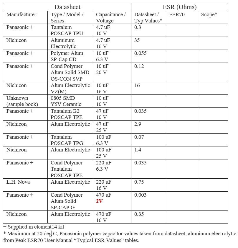
The Peak ESR70 will be used to confirm the results from the oscilloscope / function generator experiments.  It will also be used to confirm capacitance measurements from a good quality bench multimeter.  Tests will be run at room temperature, approximately 20 degrees C.  ESR-70 capacitance probes will be calibrated before starting.  The function generator square wave (100 kHz, ~3V3) and resistor divider settings will be set before starting.  The following procedure will then be followed for each capacitor:


Measure capacitance and ESR with ESR70
  1. Measure and record ESR
  2. Measure and record capacitance


Measure capacitance use of Tenma 72-102072-1020
  1. Measure and record capacitance


Measure voltages with Rigol DS1054Z and Ultrascope
  1. Measure and record open circuit voltage Vfg on oscilloscope
  2. Put the capacitor being tested in place as shown in the diagram
  3. Measure and record voltage across capacitor (ESR)
  4. Look for exponential rise / fall due to RC charge / discharge as shown in diagram and other anomalies.  Record with screenshot.


   NOTE:  A Siglent SDS 1102CML 100 MHz oscilloscope was ultimately used in the actual experiments


Calculate ESR with formula (1)


Discussion of Error


None of the instruments being used have calibration certificates and all, with the exception of the ESR70, have been in use for more than a year.  Some pertinent specifications from the instrument manufacturers are given below.

image


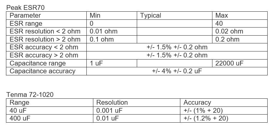
Testing methods and termination used for ESR measurement with the oscilloscope could introduce error.  The ESR model used is relatively simple and inductance / parallel resistance is not accounted for.  Accordingly, accuracy and resolution for the oscilloscope method has not been determined.


Report Format


Screenshots and video will be made as appropriate for the experiment.  Results will be recorded in a spreadsheet style tabe with data similar to that listed below for each capacitor evaluated.

imageimage


Results will then be plotted and summarized as appropriate in written form along conclusions drawn.
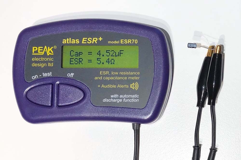
 

A Peek Ahead


Shown below, the Peak ESR70 measuring a 4.7 uF aluminum electrolytic....

image

The same 4.7 uF aluminum electrolytic being driven with a 100 kHz square wave is now viewed on the oscilloscope.  The lower blue trace is the square wave and the upper yellow trace shows the voltage drop across the capacitor (ESR) as indicated by the two white lines drawn in and labelled. 

image

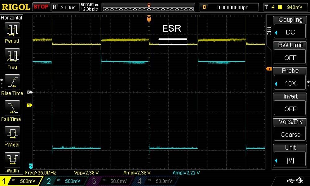
The methodology is still being worked but the calculated ESR is roughly 7 ohms with the oscilloscope method and 5.4 ohms with the Peak ESR70.  It probably will  not be possible to measure very low ESR with the oscilloscope.


Thanks for the interest - your comments, suggestions and corrections are always appreciated.

Links

  • Deep Dive into ESR, Testing
  • Deep Dive into ESR,  Application
  • AD9850 Frequency Generator Booster Pack
  • Sign in to reply

Top Comments

  • michaelkellett
    michaelkellett over 6 years ago +6
    One of the caps in your kit is 220uF with a claimed ESR of 0.009 ohms (I didn't check them all). At 100 kHz the impedance of an ideal 220uF cap is 0.007 ohms, which is significant. Since one of the benefits…
  • jc2048
    jc2048 over 6 years ago in reply to fmilburn +5
    How many capacitors do you have? If you've got ten of the same type and value, perhaps you could try soldering them in series, measure the ESR with the meter, and then divide the reading by ten to get…
  • michaelkellett
    michaelkellett over 6 years ago in reply to michaelkellett +5
    Here's another paper, showing a better way but using some much more pricey gear (about $5000 for the main box). https://www.omicron-lab.com/fileadmin/assets/Bode_100/ApplicationNotes/Capacitor_ESR_Measurement…
Parents
  • michaelkellett
    michaelkellett over 6 years ago

    One of the caps in your kit is 220uF with a claimed ESR of 0.009 ohms (I didn't check them all).


    At 100 kHz the impedance of an ideal 220uF cap is 0.007 ohms, which is significant.


    Since one of the benefits of polymer caps is ultra low ESR, allowing them to replace ceramics which are also very good, you will need a very different measuring technique to measure them.

    Sadly the Peak ESR70 is not up to it.


    There is a good thread here:


    https://www.eevblog.com/forum/projects/measuring-ultra-low-esr-caps/


    The DE-5000 looks interesting.


    MK

    • Cancel
    • Vote Up +6 Vote Down
    • Sign in to reply
    • More
    • Cancel
  • shabaz
    shabaz over 6 years ago in reply to michaelkellett

    Hi Michael,


    I wonder if the Peak allows selection of frequency, then an approach could be to measure ESR at a few lower frequencies, e.g. 120Hz, 1kHz, 10kHz, and then  compare with ceramics, aluminium electrolytics, etc., at those same lower frequencies. It doesn't show the best ESR they are capable of though.

    Or, maybe using circuits that exhibit degradation if the ESR is not extremely low, and monitor that, instead of directly measuring the ESR. I'm thinking something like a ADC chip (e.g. sound card) and examine the digitized result with different capacitors attached for decoupling. But I'm just guessing if this is useful or not, it may be inconclusive and not provide much information : (


    The DE-5000 looks very cool - I have another Chinese-made LCR meter (a desktop one, I forget the model number, the manufacturer is called Eucol) but I'm still learning how to use it. I'll report back if it is any good.

    • Cancel
    • Vote Up +4 Vote Down
    • Sign in to reply
    • More
    • Cancel
  • fmilburn
    fmilburn over 6 years ago in reply to jc2048

    Hi Jon,


    Clever and I had not thought of it. .. Unfortunately there are only 1-2 caps of each type and value. 


    Frank

    • Cancel
    • Vote Up +1 Vote Down
    • Sign in to reply
    • More
    • Cancel
  • michaelkellett
    michaelkellett over 6 years ago in reply to shabaz

    Hello Shabaz,


    I've been thinking about it (mainly while walking the dog -she's getting very fit !) and I've got some ideas but no quite ready to put on paper yet.


    I notice that even pricey boxes like the B&K 1MHz LCR that Farnell sell can't really cope down at ESR < 10mR. Their box can only do about 60mA test current but it seems to me that 500mA or more is needed for low ESRs.

    Then there are other issues that get in the way, like lead and contact resistance being bigger than the ESR we are measuring.


    The upshot is that a system that can cope with caps from maybe 1uF to 100mF and ESR from 10R to 1mR is not going to be simple - so I'll go on thinking but I'm not sure I'll ever make one.


    MK

    • Cancel
    • Vote Up +3 Vote Down
    • Sign in to reply
    • More
    • Cancel
  • jw0752
    jw0752 over 6 years ago in reply to jc2048

    Hi Jon,


    I was fascinated by your suggestion to put multiple caps in series to produce a measurable ESR and then divide by the number of caps to get the average. I have run some experiments to see if this would in fact work out. Keep in mind that the equipment that I am using is not suitable for lab work. I used (7) 474  0.47 uF ceramic 50 volt caps and I measured each one separately to obtain its ESR. I then put them in series and once again measured them. I did this at several different frequencies and in all cases the measured ESR of the series string was about 80% of the individual ESRs added together. There was some consistency with about a 4% difference from 1 kHz to 100 kHz. I am doing some reading now to see what I can learn from this. If anyone wants to pursue this experiment further let's pull it into its own thread so we don't needlessly clutter Frank's Blog.


    John

    • Cancel
    • Vote Up +3 Vote Down
    • Sign in to reply
    • More
    • Cancel
  • jc2048
    jc2048 over 6 years ago in reply to jw0752

    Interesting experiment (I didn't expect anyone to actually try it). In theory it should work. If you are genuinely measuring the ESR, then it's a pure resistance and they should simply add when put in series. But as this thread already shows, measuring low ESRs separate from other things doesn't sound like it's exactly a trivial thing to do.


    One advantage of measuring the series group is that the inaccuracy due to any lead and contact resistance from the test equipment decreases as a proportion in the measurement (assuming you can make good low-resistance and low-inductance connections between the individual parts).


    But it is just an average, so it gives some general idea of the kind of value for a batch of components but isn't really a substitute for measuring an individual part.

    • Cancel
    • Vote Up +1 Vote Down
    • Sign in to reply
    • More
    • Cancel
  • jc2048
    jc2048 over 6 years ago in reply to fmilburn

    It's not really clever. It derives from advice to parallel capacitors to reduce the effective ESR. If you parallel two similar caps then, approximately, it's like you've doubled the capacitance and halved the ESR (the overall ESR looks to be half because they each share half the current and each cap then generates half the ESR voltage that it would with the full current).

    • Cancel
    • Vote Up +1 Vote Down
    • Sign in to reply
    • More
    • Cancel
Comment
  • jc2048
    jc2048 over 6 years ago in reply to fmilburn

    It's not really clever. It derives from advice to parallel capacitors to reduce the effective ESR. If you parallel two similar caps then, approximately, it's like you've doubled the capacitance and halved the ESR (the overall ESR looks to be half because they each share half the current and each cap then generates half the ESR voltage that it would with the full current).

    • Cancel
    • Vote Up +1 Vote Down
    • Sign in to reply
    • More
    • Cancel
Children
No Data
element14 Community

element14 is the first online community specifically for engineers. Connect with your peers and get expert answers to your questions.

  • Members
  • Learn
  • Technologies
  • Challenges & Projects
  • Products
  • Store
  • About Us
  • Feedback & Support
  • FAQs
  • Terms of Use
  • Privacy Policy
  • Legal and Copyright Notices
  • Sitemap
  • Cookies

An Avnet Company © 2025 Premier Farnell Limited. All Rights Reserved.

Premier Farnell Ltd, registered in England and Wales (no 00876412), registered office: Farnell House, Forge Lane, Leeds LS12 2NE.

ICP 备案号 10220084.

Follow element14

  • X
  • Facebook
  • linkedin
  • YouTube