


Recap: I am building a wireless vitals sensor node (heart rate, SpO₂, temperature) that reports over BLE into Home Assistant as your smart way to keep watch over our loved ones, built up in three phases — DK bring-up, a custom miniaturized nRF52832 PCB, then a Matter over Thread proof of concept.
Past Posts
Past few Design challenges were leaning on Analog Devices parts, and was very much interested in getting to know another one. I did get my kit delivered on 18th Sept. Thank you e14Liz and JoRatcliffe for the logistical support and for adding the Cap, Stickers and the Badge. Here is an unboxing video instead of an unboxing post. Apologies for bad framing.
Music by MiroMaxMusic from Pixabay
The MAX30208EVSYS dev board
MAX30208EVSYS# the kit contains the interface board along with the MAX32630 Feather board. THe Sensor itself is on a small flex cable that plugs into a separate interface board rather than as a bare chip on a breakout.

The official document's say this allows for "'Sense Temperature Away from Extra Circuitry" and "Low Thermal Mass Allows for Fast Response Time", Technically they are correct but the low thermal mass is not applicable. The Datasheet of MAX30208 mentions that the sensing area is on the top part of the sensor and this sensor being meant for a wearable device means, the sensor should touch the skin surface through a heat conducting medium. Think of the digital thermometer we have at home, it has a metallic tip that transfers the heat from the skin to the sensing element inside until the sensing element is at the same temperature as the skin.
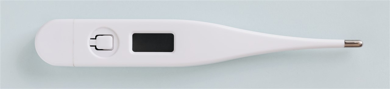
Pic Credit: www.magnific.com/.../white-digital-thermometer-gray-background_26677804.htm
What actually sets response time is the thermal mass of whatever sits between skin and the sensing element for the thermometer, that's the metal tip; for us, it'll be whatever couples the flex-mounted sensor to skin. The flex cable itself isn't in that path at all, it only carries the sensor's electrical connection back to the interface board, so its own low mass doesn't speed up anything thermal. So "low thermal mass" in the datasheet seems to be a marketing pitch not an actual function.
The real technical requirement of flex sensor is that it should be insulating thermally and allows the sensor to be positioned easily to measure a skin's temperature via a proper material just like the tip. And this is where the Multicomp Pro Adhesive thermally conductive tape MPGCS-008T-300-0.25 comes. I can use it as an adhesive tape to stick the top of the sensor to a small copper strip which will touch the human skin.
Analog Device's Evaluation boards gives a Developer lot of options but also are not easy to get started and I've seen their documentation being cryptic sometimes. This board has a DS2484, but I can't figure out what it's function is. The Jumpers documentation is not to standard levels for this particular board.
Relevant jumpers:
| Jumper | Function | What I did |
|---|---|---|
| J3 / J4 | Gate the onboard 4.7kΩ I2C pull-ups | Keep Shunted. |
| J6 | Something to do with DS2484 | Kept it at I2C Part |
| J7 / J8 | Connects the SDA SCL Pins to the Feather Compatible pins | I Shunted I2C lines to IO Lines. |
If you are connecting the MCU using the J10 connector then J7/J8 Connector is irrelevant.
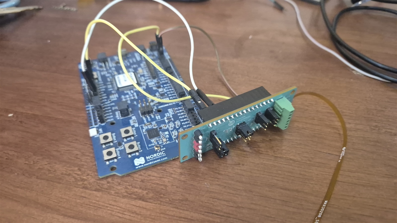
The Sad part is that the flex cable itself only breaks out four of the sensor's ten pins to the interface board's header: VDD, GND, SDA, SCL. The MAX30208 is a 10-pin Thin LGA with two extra pins, GPIO0 and GPIO1, that can optionally act as an interrupt output and an external convert-trigger input — neither is wired on this flex, so Temperature can only be polled. Meaning, I can't keep the MCU sleeping until the sensor wakes it up when temperature crosses a limit. Bye Bye Low power programming.
Learning from the reference drivers before writing one
Before touching nrf_drv_twi, I read through existing driver to make sure I understood the register sequencing, not just the pin map. There is no Arduino or Open Source library available:
Maxim's own MAX30208EVSYS reference driver mirrored from analogdevicesinc/LowPowerMicroExamples does: write Setup (start a conversion) → read Status → read FIFO Data. This has a TEMP_RDY bit but the sample driver never checks the conversion-ready bit before reading FIFO Data, it just gates on a fixed 50ms loop delay. Probably because in the Datasheet (Page 8) the following is mentioned
Do not sample at more than 20Hz, as the total time for a sample to be ready after sending a conversion command can be up to 50ms. Following the conversion, which takes 15ms(typ), the resulting temperature data is store in the FIFO and the device returns to the standby state. CONVERT_T automatically clears to ‘0.’
What it actually takes to read a temperature
Four registers, from the MAX30208 datasheet's register map:
| Register | Address | Access | Purpose |
|---|---|---|---|
| PART_ID | 0xFF | read | Identity check, expect 0x30 |
| STATUS | 0x00 | read | Bit0 = TEMP_RDY, set when a conversion finished |
| TEMP_SENSOR_SETUP | 0x14 | write | Bit0 = CONVERT_T, self-clears, starts a conversion |
| FIFO_DATA | 0x08 | read, 2 bytes | The 16-bit result, MSB first |
Sequence: write 0xC1 to TEMP_SENSOR_SETUP — bit0 starts the conversion, and bits 7:6 are RFU but the datasheet requires writing them as 1, hence 0xC1 rather than just 0x01. Then poll STATUS until TEMP_RDY comes back set (typ. 15ms, up to 50ms per the datasheet — I used a 75ms timeout, 25ms of margin over that 50ms max), and finally burst-read the two FIFO_DATA bytes.
The driver
Built a small shared I2C helper first — firmware/lib/i2c_bus.c — because by this point I had three different pieces of code (max30102_stream, twi_scanner, and now this) each hand-rolling their own twi_init()/read_reg()/write_reg() against nrf_drv_twi. One helper, sensor drivers just implement their register map on top.
The MAX30208 driver itself (firmware/lib/max30208.c) is short — trigger, poll, read, sign-extend:
ret_code_t max30208_read_temperature(float *temp_celsius)
{
    uint8_t raw[2];
    int16_t raw_temp;
    ret_code_t err_code;

    err_code = i2c_bus_write_reg(s_dev, REG_TEMP_SENSOR_SETUP, SETUP_START_CONVERSION);
    if (err_code != NRF_SUCCESS) return err_code;

    err_code = wait_for_conversion_ready();
    if (err_code != NRF_SUCCESS) return err_code;

    err_code = i2c_bus_read_reg(s_dev, REG_FIFO_DATA, raw, sizeof(raw));
    if (err_code != NRF_SUCCESS) return err_code;

    raw_temp = (int16_t)(((uint16_t)raw[0] << 8) | raw[1]);
    *temp_celsius = (float)raw_temp * TEMPERATURE_LSB_C;
    return NRF_SUCCESS;
}
wait_for_conversion_ready() polls STATUS.TEMP_RDY in a loop, returning as soon as it's set rather than always waiting out the full 75ms timeout — most conversions finish close to the 15ms typical, so this gets the reading back well before the worst case. Even without an interrupt to sleep on, that still matters: less active polling time before the MCU can consider dropping back to a low-power state between samples.
SCL stuck low — chasing a real bus lockup
Once I had this wired up and started testing, I got on of two failures. Sometimes NRF_ERROR_DRV_TWI_ERR_ANACK which means No Acknowledgement and sometimes the whole thing just hung, the blocking TWI call spinning forever inside the SDK's own busy-wait, never returning at all.
Checked the usual Continuity Check, Pullups and the idle Voltage level on bus line. SCL Was stuck at 0.4V. I removed the power and I2C lines and rewired it to my MAX30102 Breakout board, the Sensor was seen in the I2C Scanner. Then using an Logic analyzer I saw that the SCL is clamped low the second, the board received it's power, even well before the I2C transaction starts. So I was sure that this has nothing to do with the I2C helper function which I wrote.
Even with a breakpoint at the start of the firmware with the NRF52 core stopped, the SCL went down. It remained low with only with the power pins attached to the MAX30208EVSYS interface board. I removed the MAX30208 Flex cable, the problem persisted. Now it's clear - The Culprit has to be the DS2484 or the J6 Jumper misconfiguration. I opted to simply removing the DS2484 IC. and et Voila - SDA and SCL lines are high on Idle
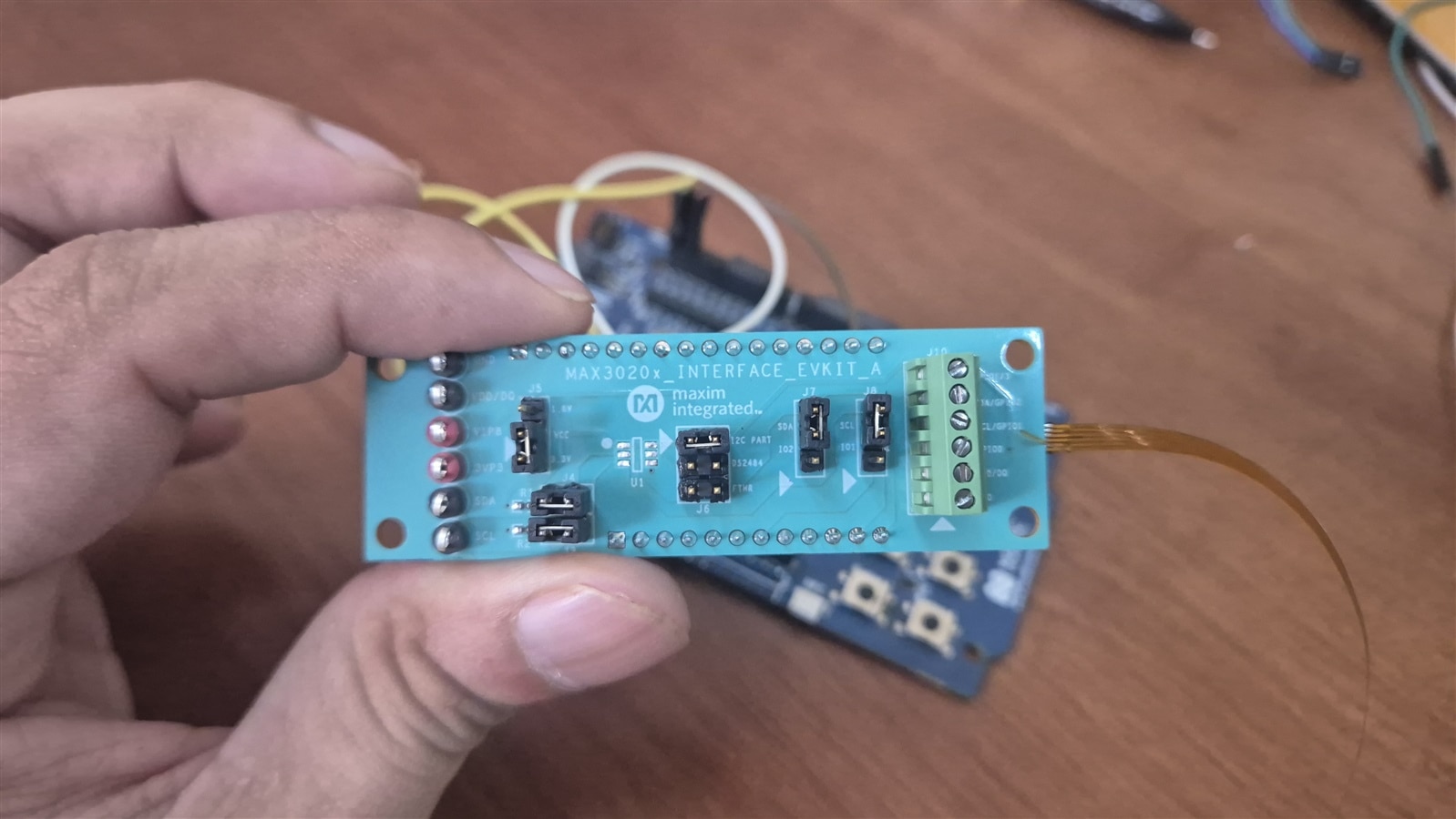
DS2482 Removed
Then came an another error - NRF_ERROR_BUSY. This is a well known complaint on Nordic DevZone going back years, and while Nordic did eventually fix the busy-flag-not-reset case in nrfx itself, that fix never made it back into the legacy nrf_drv_twi wrapper in the SDK Which I am using (SDK 17.1.0). The fix is a full nrf_drv_twi_uninit()/init() cycle, confirmed by reading nrfx_twim_init()'s own source. Two changes to i2c_bus.c fixed it for good: i2c_bus_init() now waits 200µs after enabling the TWI peripheral before any real transfer and do_xfer() below auto-reinits the driver whenever a transfer times out, so a stuck transfer self-heals instead of wedging every later call for the rest of that boot:
/* A stuck bus spins forever inside nrf_drv_twi's own blocking mode --
 * it busy-waits on a hardware event that never arrives. Run the driver
 * in async/interrupt mode instead and enforce the deadline ourselves. */
#define XFER_TIMEOUT_US 100000 /* 100ms: generous over any legitimate clock-stretch */

static ret_code_t do_xfer(nrf_drv_twi_xfer_desc_t const *xfer)
{
    s_xfer_done = false;
    ret_code_t err_code = nrf_drv_twi_xfer(&m_twi, xfer, 0);
    if (err_code != NRF_SUCCESS) return err_code;

    for (uint32_t waited_us = 0; !s_xfer_done; waited_us += XFER_POLL_INTERVAL_US)
    {
        if (waited_us >= XFER_TIMEOUT_US)
        {
            reinit_after_stuck_transfer();  /* full uninit+init, clears the wedged busy flag */
            return NRF_ERROR_TIMEOUT;
        }
        nrf_delay_us(XFER_POLL_INTERVAL_US);
    }
    return s_xfer_result;
}
With this fix, I was seeing temperature readings, touching the top part of the sensor by pinching the sensor between two of my fingers, saw the temperature rising.
Testing - with and without the thermal tape
To see how the sensor responded with and without the tape, I did three scenarios -
- Pinch 1 - Pinch hard
- Pinch 2- gentle pinch,
- Gentle pinch with adhesive tape in between
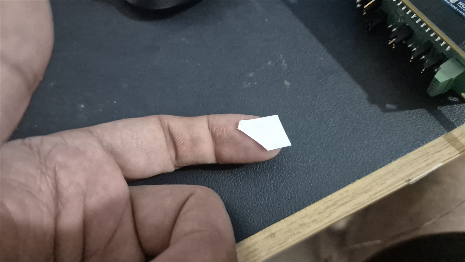
In all three cases, I let the temperature climb, stabilize and then removed my fingers and watch it settle back to ambient temperature. I am not going to characterize at an instrumentational level so I took only one readings each.
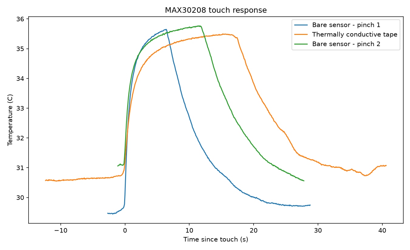
With Ambient around 29.3°C, the values climbing to 35.5–35.8°C on a finger pinch across all three trials which is quite expected. The difference is response time: with the tape on, it took about 34% longer to reach 90% of the eventual rise, and roughly 2x longer to decay back toward baseline after release. Just as what I said above, the tape adds thermal mass and thus needs time to transfer extra heat to bring the sensor as well the the tape itself to same temperature. The Copper plate once I add will change the numbers further. It is not going to affect our final wearable device as since it is going to be a continuous monitoring device, once worn the sensor will reach equilibrium with skin and and since body temperature will change slower (even in case of fever) than the responsive time of the the wearable, there is no problem.
Code
The Full code for all the posts till now will be at https://gitlab.com/arvindsa/vitarf-e14
Final notes
Both sensors done and tested. The DS2484 has absolutely no function to do with MAX30208. It seems to be an artifact of using the same board for a family of sensors as supported by the Silkscreen "MAX3020X Interface". I now have to quickly design a PCB and send it off.