


EdgeCare: phase 1 - setup IDE, MCU and BLE - element14 Community
EdgeCare: phase 2 - setup I2C, read MAX30100 and create VI in LabView - element14 Community
EdgeCare will be a Multi-Sensor Metabolic & Autonomic Datalogging Wearable with LabVIEW R&D Analytics.
Important: this phase 4 normally should be used to create a PCB for the project, optimise the code and add a small power supply toithe bracelet.
Because the issue with EORI code (I wait for the components for one month), the full schematic including the power supply, PCB and enclouser will be done after the contest; the same with the final shape and type for the dry sensors.
In this post I will present two things:
- save data from LabView on the PC in the excel format;
- connect the LabView to my smart home based on NodeRed
A. Save data from LabView to the PC in excel format
Saving the data is a good thing because they can be analyzed for bebuging, improvment of the system behavior and long time observations.
To achive this I chosen to save data in excel format directly from LabView.
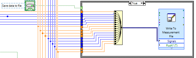
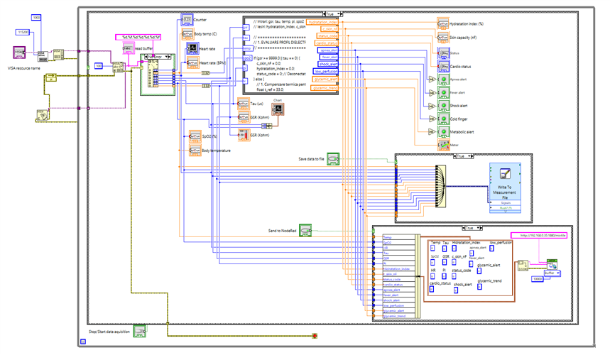
For that I added the "Write to measurement file" block; inside I set the file path were the file will be saved (this is generic and can be modified);
Because i have 16 signals + timestamp, I used "merge signals" block to gather all the signals in one entrance, to be sabed in the excel file.
I added also an button to start/stop the saving data; this button/option is used especially in the development phase:
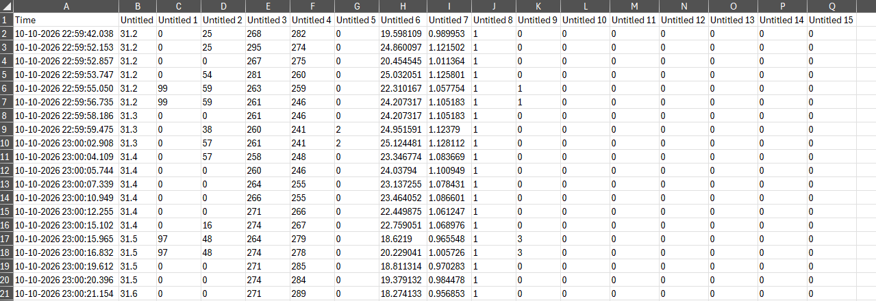
OBS: it is not easy to set the name of the signals saved in the top of each column in LabView; that why I modified the original file with the signal names and then, for analisys, the first from the log file will be replaced with the modified one:

B. Connect the LabView to my smart home based on NodeRed
After configuring all the parameters, I thought it would be useful to integrate this system with an smart home environment, to have all these information available in one place.
This "Smart Home" project runs on a Mixtile Edge 2 PC kit—using Debian Linux and a Node-RED environment.
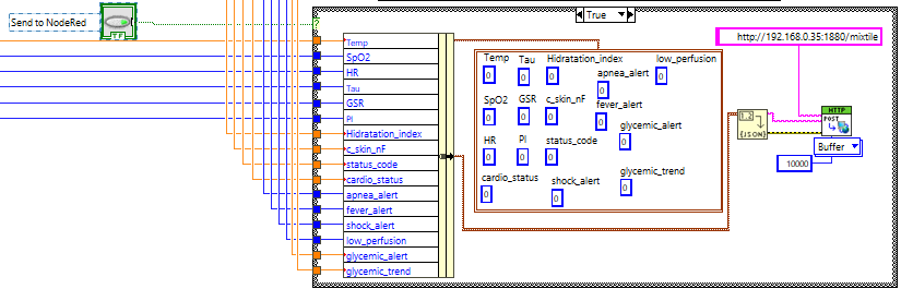
Communication with this PC—and by extension, the smart home/Node-RED system—takes place via the HTTP protocol, as it is much easier to configure in LabVIEW than MQTT.
I added a button in LabVIEW to toggle data transmission to Node-RED; this is useful for debugging and development, but especially for handling situations where Node-RED is shut down (otherwise, LabVIEW would generate a series of communication errors).
Link with my Smart house project: My Smart house project
Here is the communication implementation:
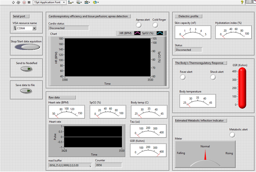
Now, this is the final LabView panel and implementation:
NodeRed implementation and panel:
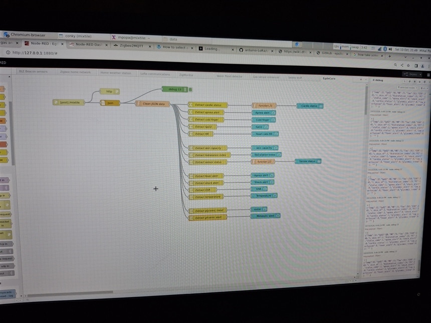
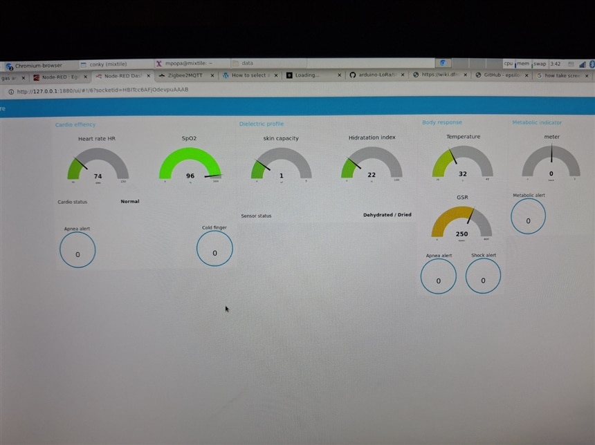
The code used in NodeRed will be available in the final project post.
Demo:
Next: replace the max30100 and DS18B20 sensors with the ones received from element14 and finalize the bracelet...