


This project is to solve an everyday problem I have. I am frequently forgetting to arm the alarm when I leave the house. You can have the best alarm in the world, but what use is it if it is not turned on when you need it?
While I get an audio reminder to disarm the alarm as soon as I open the front door, there is no such reminder when I leave. Even if there was a door sensor, how would it know if I wanted the alarm setting or if I was just going to the garden. What I needed to do was create a device to identify when everyone has left the property and then set the alarm. Simple as that. I am very keen on keeping things simple. (* may not be 100% true)
My solution monitors for the common “Key Finder” Bluetooth tracker on my keys and identifies if it, and all the others tags it knows about, have gone out of range. If they have all gone then no one is home and the alarm should be set.
No complicated app on the phone. Nothing new to learn. If you have a compatible Bluetooth tracker on your keys already then you don’t need anything extra.
The Hardware
At the heart of the solution is the MAX32630FTHR that has been supplied for the challenge. This has the required BLE capability to scan for my common bluetooth tracker along with other types. It will not work with trackers that use a rotating MAC address, and that excludes the Apple AirTag and the Samsung Galaxy SmartTag, but most low cost Bluetooth key and pet finders should work.
For connectivity to the alarm system I have used the supplied Particle Ethernet Featherwing to talk to the Internet, and a donationware service to link to Amazon Alexa. At first this might seem an odd solution, but there is a good reason for it that I will explain later.
The Build - Overview
In summary, I made it and it works. It works well, but it took a lot of problem solving to get here. I am typing this with a working system with a whopping 4-days before the challenge deadline, so we can even pretend it was ready ahead of schedule. (future me note, there are still hours remaining as proof read this, so I am still counting it as ahead of schedule) ;-)
It has been quite enjoyable working on the problems, but there were many problems. There were two root causes of these. The first being the MAX32630FTHR is intended for use with the Mbed platform, but the online compiler is shutting down in July this year, so I decided to use the Arduino core instead. There is nothing wrong with this core, but it is old and has not been refined as most people used Mbed instead. The second is an unlucky pin selection for the Bluetooth module.
Below is a summary of my build. If you just want to jump straight in and recreate the build then the full source code is available on GitHub at https://github.com/alistairuk/dont-forget-to-set . You just need to add the MAC addresses of your trackers (from the tracker packaging or app), and the URL to set your alarm (details below).
The Build - Programming the MAX32630FTHR
The MAX32630FTHR is a great little board, but the mbed platform closing later this year I wanted to use another platform. I wanted this to be accessible to everyone I opted to use the Arduino platform.
It may come across at times here that I regret this decision, but that is not true. There have been several issues relating to it, but I managed to work through them all and although it would have been easier to quickly code this using mbed, having solved those problems they are solved going forward for other projects.
I did a full walk thought with screenshots on how to do this in a design challenge forum post Programming the MAX32630FTHR with the Arduino IDE.
The Build - Accessing the PAN1326B Bluetooth module

Now things start getting interesting. I knew when taking on this project that I was likely going to have to get my hands dirty with some HCI commands, but I did not realise the technical challenges I would need to overcome before I could send these HCI commands to the module.
Most of the issues stemmed from using the Arduino core. There are a lot of things in the Arduino world that are done for you that make using the hardware easier and more accessible, but occasionally they are doing things you do not want to happen and have the opposite effect.
The first challenge is to initialise the UART for communication (including the correct RTS and CTS pin mappings) and enable the 32768Hz oscillator output on P1.7.
Another thing to note from the MAX 32640 errata sheet is that P1.6, that is used to reset the PAN1326B, has unexpected functionality when the oscillator output is used, so our order of operation becomes critical.
In summary this will get you up and running. Remember the order is important.
#include <pwrseq_regs.h>

// PAN1326C2 HCI UART (use Serial 0 on MAX32630FTHR)
#define BT_SERIAL Serial0
// PAN1326C2 reset pin
#define BT_RST P1_6

// Reset (and hold) the PAN1326B
pinMode(BT_RST, OUTPUT);
digitalWrite(BT_RST, LOW);

// Enable the 32768Hz Oscillator Output on P1.7 (from 4.5.1.5.2)
MXC_PWRSEQ->reg4 |= MXC_F_PWRSEQ_REG4_PWR_PSEQ_32K_EN;
delay(HARDWARE_SETTLE_TIME);

// Initialize UART0 for PAN1326B communication
BT_SERIAL.begin(115200);
// Swap the RX/TX lines and enable CTS & RTS
MXC_IOMAN->uart0_req |= MXC_F_IOMAN_UART0_REQ_CTS_IO_REQ | MXC_F_IOMAN_UART0_REQ_RTS_IO_REQ | MXC_F_IOMAN_UART0_REQ_IO_MAP;

// Enable the PAN1326B
// Note that P1_6 may already be high (input with an internal pullup) after we enables the oscillator output
digitalWrite(BT_RST, HIGH);
Again I will not fully document this fully here or this post will be so long no one will read it, but I have created a how to forum post Accessing the PAN1326B Bluetooth module with the Arduino IDE that covers how to do this.
Yet another oddity is the PAN1326B will often not respond after a power cycle. I only realised this recently as everything ran after the firmware was uploaded, but plugging the build in without a computer attached was not working. Resetting the platform with the reset button twice in quick succession fixed the issue, and as a quick fix I was going to add a separate watchdog MCU to do that, but then I found that just resting the Arm core once while leaving the rest of the module configured worked and detecting when that was needed is easy.
Here is some code that you should be able to transplant into your project easily enough.
// HCI Command to reset the PAN1326C2
const byte hciCommandReset[] = {0x01, 0x03, 0x0C, 0x00};

// Send the software reset HCI command
BT_SERIAL.write(hciCommandReset, sizeof(hciCommandReset));

// Timeout for PAN1326C2 to respond after boot
#define HARDWARE_BOOT_TIME 1400

// Delay to allow PAN1326C2 and 32768Hz oscillator to settle
#define HARDWARE_SETTLE_TIME 200

// Wait for response (and reset if it has stalled)
while (!BT_SERIAL.available()) {
  if ( millis() > HARDWARE_BOOT_TIME ) {
    Serial.println("Stalled so rebooting...");
    delay(HARDWARE_SETTLE_TIME);
    // Reset the ARM core
    NVIC_SystemReset();
    // We should have rebooted by now
  }
  delay(HARDWARE_SETTLE_TIME);
}
This is better documented in the firmware source code with comments and it is well worth a read thought if you ever have the same issues.
Now we are able to communicate with the PAN1326B and can send basic commands, we need to apply a firmware patch to enable BLE functionality, and as this is not stored in flash we need to do this every power cycle. Fortunately TI supplied the patch already rendered into a C header file. I have tidied this up and made it Arduino compatible in the CC256XB.h file.
Yet again I have created a how to post on the form Updating the PAN1326B Bluetooth module firmware and scanning for BLE devices.
The Build - Using the Particle Ethernet Featherwing
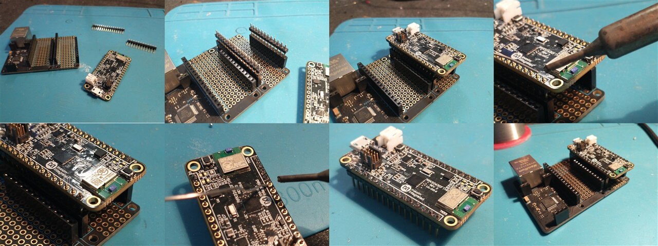
As part of this project we need to communicate without an external alarm system, and as documented below this is done using Alexa integrations. To achieve this we do however need to access the Internet. We were supplied with the Particle Ethernet Featherwing, an Ethernet adapter based on the WIZnet W5500. I have used Particle hardware and Ethernet adapters based on the W5500 so I did not see any problem, but what I did not think about is the Arduino core for the MAX32630FTHR was created a long time ago when the network abstraction in the Arduino ecosystem was new, evolving, and different from today.
At the time we would have needed to use the “ethernet2” library instead of the original "ethernet" library. Today this functionality has been moved into the main Ethernet library and the Arduino core for the different microcontrollers.
To fix this properly I would need to go in and update several sections of the Arduino core for the MAX32630FTHR, copy some networking related files from another core, and then fix a number of dependency issues this created. I am never a fan of modifying a core or a common library as this can result in unexpected compatibility issues down the road.
Instead I decided to modify the original ethernet2 library and use that. It is from around the same age as the Arduino core we are using and only requires the copying of a few files and adding one extra line to our application to get it to work. Also it will not break every time there is an ethernet[1] library update. We do lose out on future updates, but there are not likely to be any we will need in this project, and the network stack is on the W5500 chip so the security risks are reduced.
For a full set of instructions see my Using the Particle Ethernet FeatherWing with the MAX32630FTHR post.
The Build - Alexa Integration
So now we actually need to do the integration with the 3rd party alarm system. While I could make this project work with my current alarm by using an unofficial API, I wanted it to be more widely accessible, easier to change the alarm system in the future, and not likely to suddenly stop working when the alarm company updates their firmware and app.
With that in mind I decided to take the unusual step of using Amazon’s Alexa. At first it may seem odd, but many alarm systems already integrate with Alexa, so by integrating my system with Alexa I by default integrate with all of these alarm systems in one move.
While I could hack an Alexa compatible smart button it is neater to create a virtual button and trigger it across the network. Also why reinvent the wheel when a few services already exist to do this. My preferred option is the URL Routine Trigger skill from Virtual Mart Home.
Integrating with Alexa using Virtual Smart Home.
Full details and setup instructions are in my post Integrating with Alexa using Virtual Smart Home.
The Build - The Enclosure

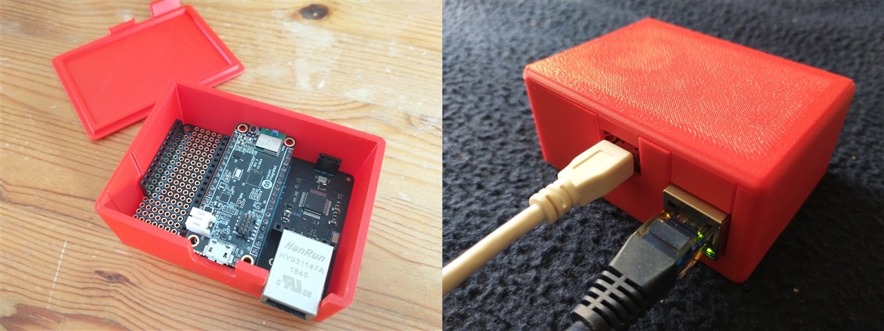
While this is a nice little extra I did like designing and printing a special custom enclosure for the hub. For a project where the cleverness is mostly in the software, it feels good to have a nice looking physical element that you can point at.
Here is a video of the prototype design printing. The final design (photographed above) evolved slightly to make assembly easier, to allow a little more room for connectors should we add a second Featherwing for any reasons in the future, and to close some holes we did not need.
The final design can be downloaded from Thingyvirse and if you want to modify it you can access the full model on Onshape.
In Conclusion
As I mentioned at the start it works well. It reliably solves my problem. It eliminates a common human error problem and brings me peace of mind.
While I was slightly embarrassed about the lack of hardware required for the build, I now realise that it is what it does that is important and I am really happy with that. Although there were so many hurdles, and times where I was questioning if it was worth solving this problem, the learning and problem solving was enjoyable and I am so happy with what I have managed.
To end with here is a demonstration video of it in action. I have taken the top off so you can see the debugging LED. When it is red it is starting up, green means there has been a known tag detected recently, and a blue flash is when any tag is detected. I configured the bulb to turn on (using Alexa) when the alarm system sets for the video. Amusingly I accidentally left this action in a screenshot on one of my how tos. To simulate the tag being away I just took the battery out. It is fairly self explanatory.