Final Build
Table of Contents
 1. Introduction
Hi! This will be my fifth and final blog for this competition since today is the 17th of November, and what better time to do something, than just before the deadline! It was a fun competition, and I'm really happy I got to participate in it. In the last blog which you can check here (Blog #4 - Measuring Blood Pressure), I covered my work with a pressure sensor that I connected to a blood pressure monitor and logged some data which I later analyzed. In this blog, I will cover the whole design and how I made the HMS (Health Monitoring Device) as well as the brand new HMS Mini, with a guest start appearing at the end of the blog! Hope you enjoy reading the blog!
2. HMS Mini
To begin, let's start with the smaller of the 2 devices that I made, the HMS Mini. Since we got the Oxi5 Click and Heart rate Click in the challenger kit, I wanted to use both of them in my project, but I couldn't use them simultaneously on the Arduino, so I decided to make the Oxi5 into its own device. As I've mentioned in the previous blogs, the Oxi5 Click uses the MAX30102 sensor, a newer version compared to the Heart rate Click which uses the MAX30100. If you're interested in the differences between the sensors, I've covered that in this blog (Blog #3 - First Prototype).
Idea
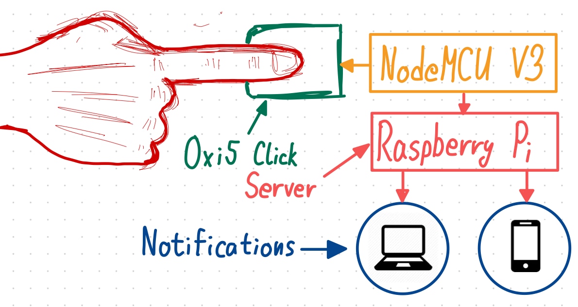
The idea for the HMS Mini is to have the Oxi5 Click connected to a NodeMCU V3 (ESP8266) with a small OLED display. Using the HMS mini you can get your heart rate reading as well as the oxygen blood saturation, and by pressing the green button, it uploads it to the server which then pushes the notification to my phone (or anyone else's who subscribed to those notifications). For the notifications to work, you don't need to install any additional apps, you can do it all from the browser which is a great plus.
Electronics
Let's begin by looking at the main components that I will be using for the HMS Mini.
| {tabbedtable}City | Component |
|---|---|
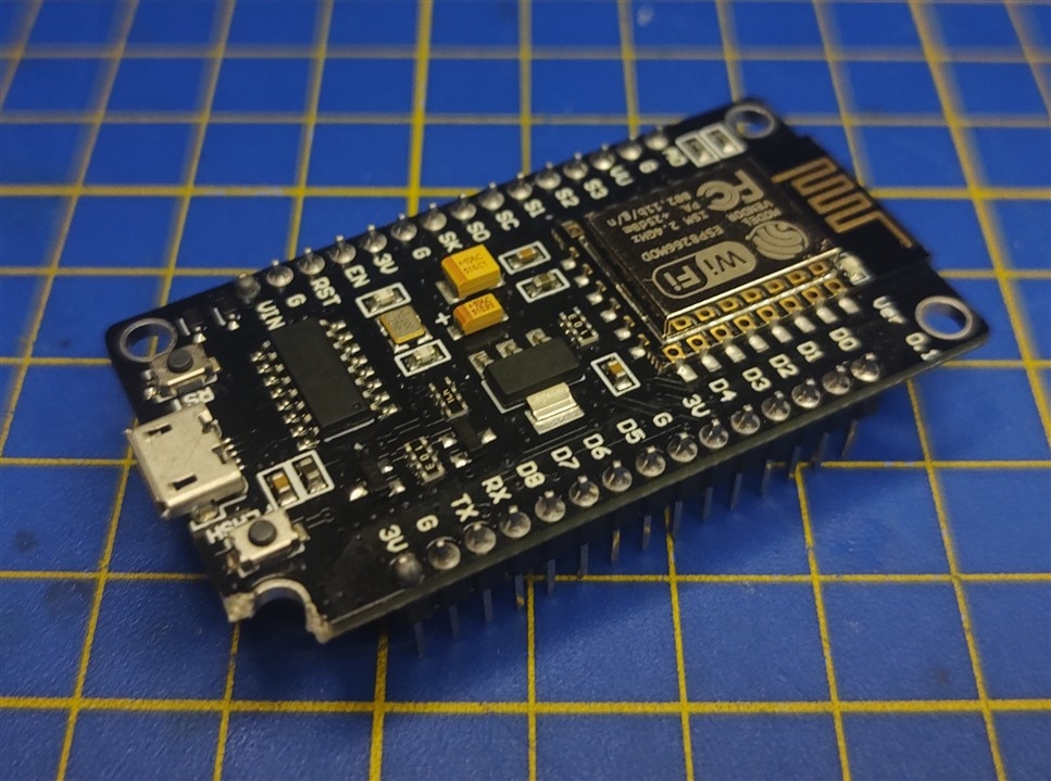
NodeMCU V3 |
This will be the main board in the HMS Mini, the Node MCU V3. Node MCU V3 houses an ESP8266 much like the Adafruit Feather Huzzah. It's a bit larger than the Adafruit Feather Huzzah, but they can essentially do the same things.
|
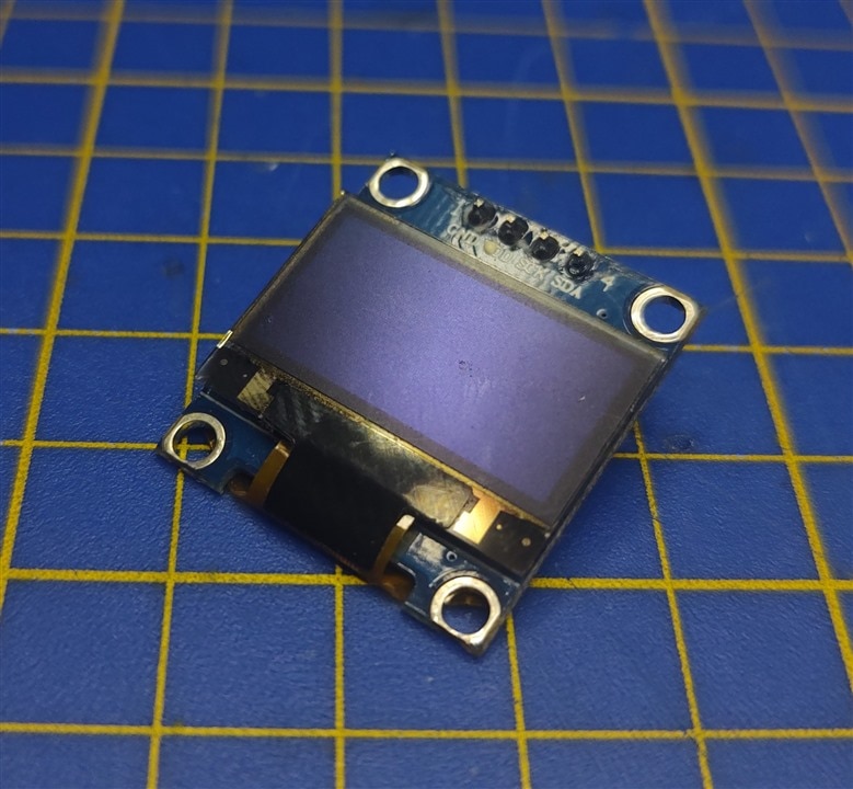
I2C OLED |
To display the data to the user of the HMS Mini, I went with one of the small, generic, I2C OLED displays. They are rather easy to use with only 2 wires for I2C and 2 wires for the power. There is an Adafruit library for them, but I went with the OakLED library since it had all I needed for this project.
|
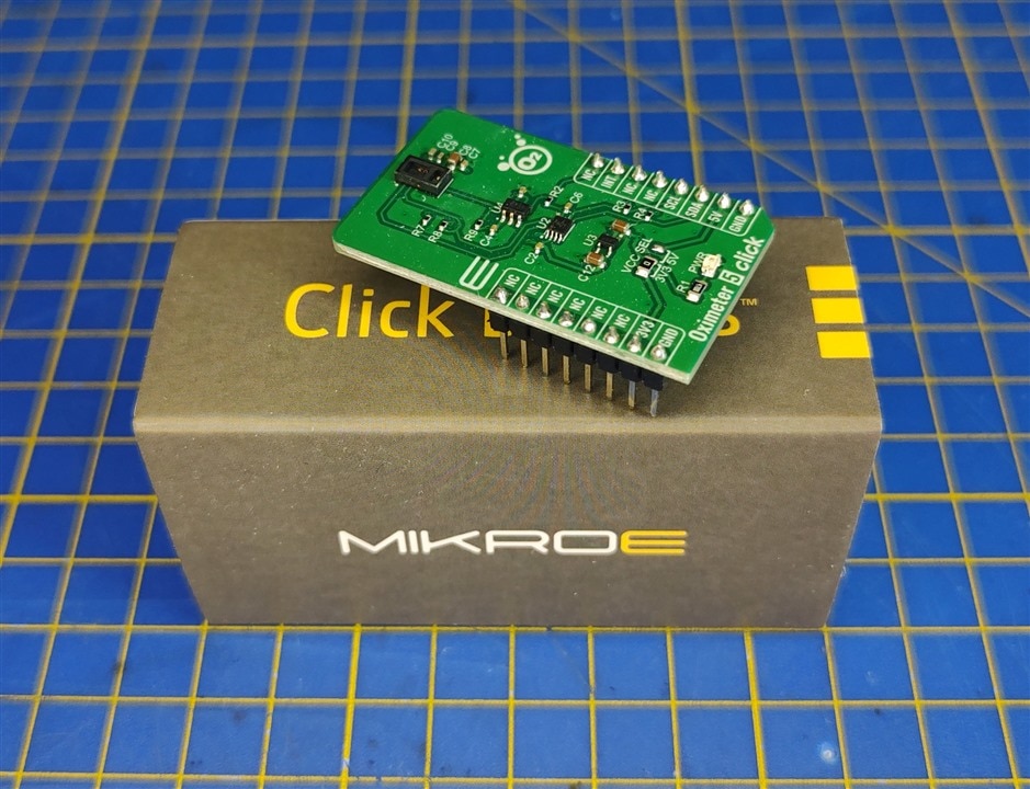
Oxi5 Click |
And in the end, we have the Oxi5 Click. I already covered this in my previous blogs. But to summarize, this Click board uses the MAX30102 sensor and can be used to measure the heart rate and the SpO2 levels. This is the part of the HMS mini that I struggled the most with on the software side, but I'll cover all of the issues in the software section for the HMS Mini.
|
Final Schematic
Besides the components I showed above, I used a couple of buttons, a switch for turning on the device and an LED to show when the device is On, and a few nylon connectors inside to try and keep it as tidy as I can. Before I get into the build section for the HMS Mini, here is the full schematic of how everything is connected.
Software
With the electronics out of the way, now we get to the software. This is the place where I had a few problems as I'll explain. First of all, the code for the HMS mini is pretty much the combination of codes from the First Prototype (Arduino + Huzzah). The NodeMCU needs to connect to the WiFi and MQTT server and then provide data readings until the user presses the button when it should then go and publish the data to the topic, so we can receive it as a notification. Before getting to the code itself, I want to cover 2 problems I came upon while working on the HMS mini.
Oxi5 Problems
The first problem I had was with the Oxi5 Click. I connect it as I've shown above on the schematic. I would then try going through examples to grab parts of the code that I need for working with the sensor. Everything worked except SpO2. I tried multiple different libraries, but every time, I got a watchdog timer error.
I tried looking for solutions online, but none helped me. So I went on and tried looking for other libraries that can work with this sensor. Up to that point, I tried the Sparkfun MAX3010x and just the MAX3010x library. Both produced the same error. Luckily, I managed to find a library by DFRobot for the MAX30102, and it worked perfectly the first time. Here is the link to that library: DFRobot MAX30102 Library.
Interrupt Problems
While the library worked great and gave me the results I wanted, it was rather slow, so I couldn't really go and try to detect the button presses in the loop. To avoid that, I wanted the button press to trigger an interrupt on the RISING edge of a signal on a pin. My first mistake was that I connected the button to the pin that doesn't support interrupts D0 on the NodeMCU, or more specifically, the GPIO16 on the ESP8266. The other issue was, that I was constantly getting an error as soon as I would turn on the board. The solution to that was to add ICACHE_RAM_ATTR before void ISR() and also keep the ISR function at the top of the code. After applying those changes, everything worked properly.
Code
#include "Wire.h"
#include "Adafruit_GFX.h"
#include "OakOLED.h"
#include <DFRobot_MAX30102.h>
#include <ESP8266WiFi.h>
#include <PubSubClient.h>

// Change the credentials below, so your ESP8266 connects to your router
const char* ssid = "SSID";
const char* password = "PASSWORD";

// Change the variable to your Raspberry Pi IP address, so it connects to your MQTT broker
const char* mqtt_server = "SERVER_IP";

// Initializes the espClient. You should change the espClient name if you have multiple ESPs running in your home automation system
WiFiClient espClient;
PubSubClient client(espClient);

/////// GLOBALS //////

OakOLED oled;
DFRobot_MAX30102 particleSensor;

int bpm = 0;
int spo2 = 0;
int valid_bpm, valid_spo2;
int32_t SPO2; //SPO2
int8_t SPO2Valid; //Flag to display if SPO2 calculation is valid
int32_t heartRate; //Heart-rate
int8_t heartRateValid; //Flag to display if heart-rate calculation is valid

volatile bool buttonPressed = false;
volatile long last_button_press;
int min_delay = 500;

ICACHE_RAM_ATTR void IRCallback()
{
  if(buttonPressed == false && millis() - last_button_press > min_delay)
  {
    buttonPressed = true;
    last_button_press = millis();
  }
}

// Don't change the function below. This functions connects your ESP8266 to your router
void setup_wifi() {
  delay(10);
  // We start by connecting to a WiFi network
  Serial.println();
  Serial.print("Connecting to ");
  Serial.println(ssid);
  WiFi.begin(ssid, password);
  while (WiFi.status() != WL_CONNECTED) {
    delay(500);
    Serial.print(".");
  }
  Serial.println("");
  Serial.print("WiFi connected - ESP IP address: ");
  Serial.println(WiFi.localIP());
  DisplayConnected();
  delay(500);
  UpdateDisplay();
}

// This functions reconnects your ESP8266 to your MQTT broker
// Change the function below if you want to subscribe to more topics with your ESP8266
void reconnect() {
  // Loop until we're reconnected
  while (!client.connected()) {
    Serial.print("Attempting MQTT connection...");
    // Attempt to connect
    /*
     YOU MIGHT NEED TO CHANGE THIS LINE, IF YOU'RE HAVING PROBLEMS WITH MQTT MULTIPLE CONNECTIONS
     To change the ESP device ID, you will have to give a new name to the ESP8266.
     Here's how it looks:
       if (client.connect("ESP8266Client")) {
     You can do it like this:
       if (client.connect("ESP1_Office")) {
     Then, for the other ESP:
       if (client.connect("ESP2_Garage")) {
      That should solve your MQTT multiple connections problem
    */
    if (client.connect("ESP8266Client")) {
      Serial.println("connected");
      // Subscribe or resubscribe to a topic
      // You can subscribe to more topics (to control more LEDs in this example)
      client.subscribe("room/lamp");
    } else {
      Serial.print("failed, rc=");
      Serial.print(client.state());
      Serial.println(" try again in 5 seconds");
      // Wait 5 seconds before retrying
      delay(5000);
    }
  }
}

/*
Macro definition options in sensor configuration
sampleAverage: SAMPLEAVG_1 SAMPLEAVG_2 SAMPLEAVG_4
               SAMPLEAVG_8 SAMPLEAVG_16 SAMPLEAVG_32
ledMode:       MODE_REDONLY  MODE_RED_IR  MODE_MULTILED
sampleRate:    PULSEWIDTH_69 PULSEWIDTH_118 PULSEWIDTH_215 PULSEWIDTH_411
pulseWidth:    SAMPLERATE_50 SAMPLERATE_100 SAMPLERATE_200 SAMPLERATE_400
               SAMPLERATE_800 SAMPLERATE_1000 SAMPLERATE_1600 SAMPLERATE_3200
adcRange:      ADCRANGE_2048 ADCRANGE_4096 ADCRANGE_8192 ADCRANGE_16384
*/
void setup()
{
  //Init serial
  Serial.begin(115200);
  pinMode(D6, INPUT);
  attachInterrupt(digitalPinToInterrupt(D6), IRCallback, RISING);

  while (!particleSensor.begin()) {
    Serial.println("MAX30102 was not found");
    delay(1000);
  }

  particleSensor.sensorConfiguration(/*ledBrightness=*/50, /*sampleAverage=*/SAMPLEAVG_4, \
                        /*ledMode=*/MODE_MULTILED, /*sampleRate=*/SAMPLERATE_100, \
                        /*pulseWidth=*/PULSEWIDTH_411, /*adcRange=*/ADCRANGE_16384);

  // OLED
  oled.begin();
  DisplayConnecting();

  // WiFi
  setup_wifi();
  client.setServer(mqtt_server, 1883);
}

void DisplayConnecting()
{
  oled.setTextColor(1);
  oled.clearDisplay();

  oled.setTextSize(4);
  oled.setCursor(0, 0);
  oled.println("WiFi");

  oled.setTextSize(4);
  oled.setCursor(0, 35);
  oled.println("WAIT");

  oled.display();
}

void DisplayConnected()
{
  oled.setTextColor(1);
  oled.clearDisplay();

  oled.setTextSize(4);
  oled.setCursor(0, 0);
  oled.println("WiFi");

  oled.setTextSize(4);
  oled.setCursor(0, 35);
  oled.println("DONE");

  oled.display();
}

void UpdateDisplay()
{
  oled.setTextColor(1);
  oled.clearDisplay();

  oled.setTextSize(4);
  oled.setCursor(0, 0);
  oled.println(String(bpm));
  oled.setTextSize(2);
  oled.setCursor(90, 8);
  oled.println("BPM");

  oled.setTextSize(4);
  oled.setCursor(0, 35);
  oled.println(String(spo2));
  oled.setTextSize(3);
  oled.setCursor(105, 40);
  oled.println("%");

  oled.display();
}


void loop()
{
  Serial.println(F("Wait about four seconds"));
  particleSensor.heartrateAndOxygenSaturation(/**SPO2=*/&SPO2, /**SPO2Valid=*/&SPO2Valid, /**heartRate=*/&heartRate, /**heartRateValid=*/&heartRateValid);

  if(buttonPressed == true)
  {
    Serial.println("Published the message to topic");
    String message = "Hear Rate: " + String(bpm) + "BPM, SpO2: " + String(spo2) + "%";
    client.publish("/measurement/clamp", (char*) message.c_str());
    buttonPressed = false;
  }

  if(heartRateValid == 1 && SPO2Valid == 1)
  {
    if(heartRate < 150 && heartRate > 40)
    {
      bpm = heartRate;
    }

    if(SPO2 <= 100 && SPO2 > 70)
    {
      spo2 = SPO2;
    }

    UpdateDisplay();
  }

  if (!client.connected()) {
    reconnect();
  }
  if(!client.loop())
    client.connect("ESP8266Client");


  Serial.print(F("heartRate="));
  Serial.print(heartRate, DEC);
  Serial.print(F(", heartRateValid="));
  Serial.print(heartRateValid, DEC);
  Serial.print(F("; SPO2="));
  Serial.print(SPO2, DEC);
  Serial.print(F(", SPO2Valid="));
  Serial.println(SPO2Valid, DEC);

}
Build
All we need to do now is assemble everything. To assemble everything required a bit of CAD modeling, 3D printing, and soldering. But assembling it from start to finish didn't take too long, I managed to go from all of the components in the morning and no CAD files to a fully working unit by the end of the day. With troubleshooting along the way if I might add.
Enclosure and 3D prints
Let's begin by looking at the mechanical parts of the build first. One thing I want to point out is that I will be publishing all of the 3D models online for free to download, and you will be able to find them on the GitHub link in the comment section as soon as I post them online. For the enclosure, I went with a Hammond Manufacturing enclosure. It's extremely sturdy and high quality and also is (was) waterproof.
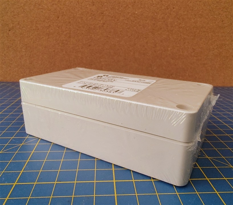
As for other mechanical parts, I only need to 3D print 2 of them. One of them is a mount for the small OLED display, while the other is a sensor guard so it can block out a bit of light that can hit the sensor so it can work better. It can also protect the sensor in case of a drop. Here are the models of these 2 parts.
Soldering
Since this is a pretty small box and I needed to fit a 9v battery inside as well, I had to get pretty creative with how I was going to cut the perf board and how I wanted to organize all of the components since there wasn't too much space. I first thought I would have to use a linear regulator, but it turned out the Vin pin on the NodeMCU V3 can handle 9V easily. Here are some pictures of the perf board inside that I soldered.
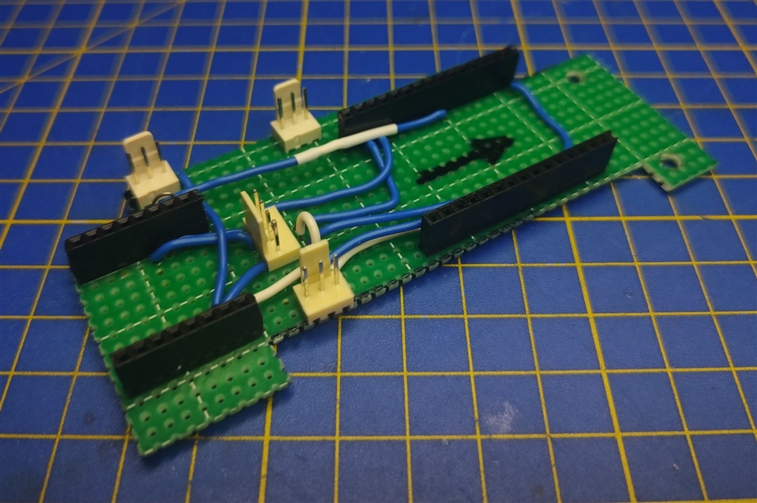
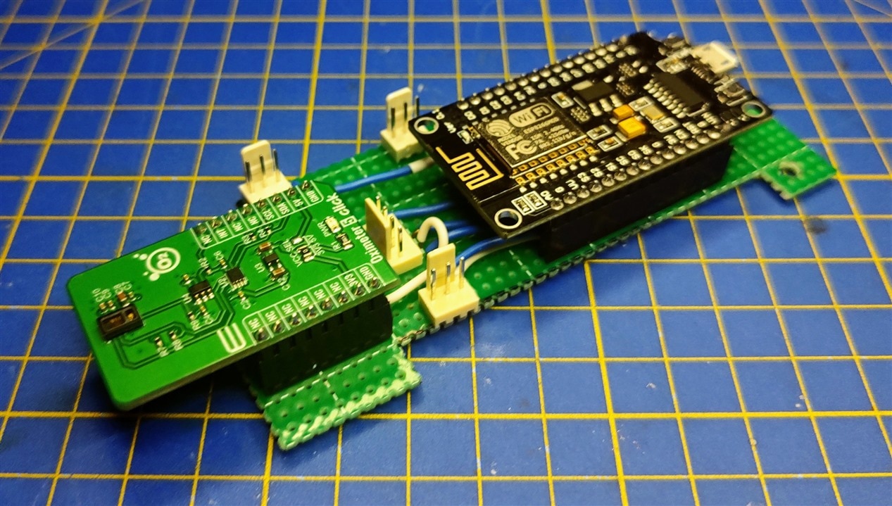
And when we add the NodeMCU and the Oxi5 Click we get this.
Final Assembly
Before we get to testing, we need to assemble everything. It's drop-in-place for the most part, the lid of the box needs some holes drilled and we need cut a hole in the body of the enclosure so that the sensor can go outside the enclosure to the user. The box is pretty small, so everything fits inside rather snuggly.
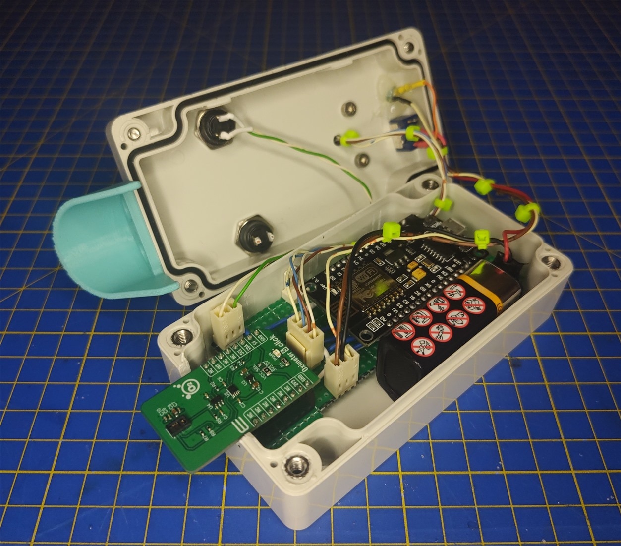
The connectors are a bit too big for the HMS Mini, and I would have rather used something like a JST connector, but these are the only ones I had on hand while working on it. Nevertheless, with a bit of cable pushing, it can be closed rather easily and secured with 4 screws, so we can get this.
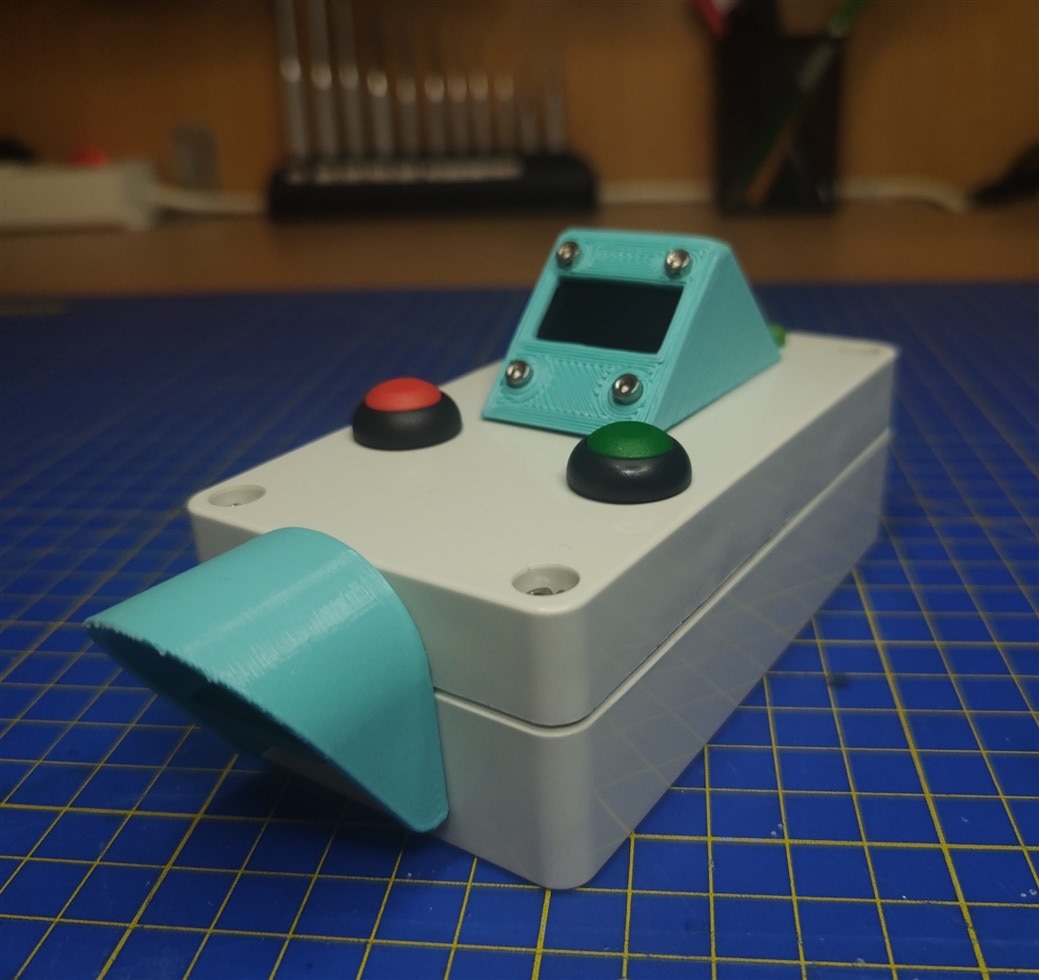
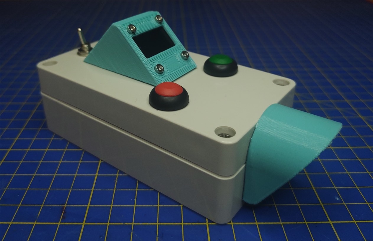
I am really pleased with how it turned out in the end! While a 3D-printed enclosure could have maybe been a bit smaller, this enclosure is incredibly sturdy and does the job really well. The only thing I would change on it is the power switch in the back since it can be rather easily triggered if the device is thrown into a bag or something. But I love how they look and feel, so those were also the only ones I had on hand that worked for the HMS mini.
Testing
All that's left to do now is the fun part, and that is to test it out to see how it works! Before I get to the video, I'll give a brief explanation of how the device is used in this version. When you turn it on, you can see a green LED in the background turn on as well as the power indicator. On the screen, there will be notifications of the device connecting to the WiFi, and once it connects, which takes a few seconds, the device is ready to use. The user can then take the measurement, and once they are happy with the final measurement, with the press of the green button, that data will be uploaded to the server which will push notifications to phones, laptops, etc. Here is a video showcasing that.
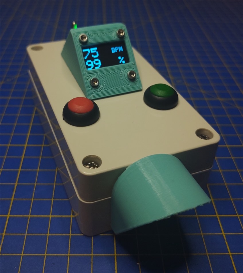
I'm really happy with how the HMS Mini turned out. The sensor needs a bit of time to get a good reading, but it gets there eventually. After testing, one thing I will need to change for sure on the HMS mini is the resistor connected to the LED, since the LED is extremely bright. Before I end with the HMS Mini, here is a picture of it in action!
3. HMS
Now we get to the bigger of the 2 devices, the HMS. Electronics for the HMS is something I have already covered in detail in my third blog (Blog #3 - First Prototype), and they haven't changed since then, but I'll do a short refresher on the whole idea of the HMS here as well as go over the build, software, and testing as I did for the HMS mini.
Idea
My initial idea for this was to have a device with a pressure sensor that can parallelly get readings with a blood pressure monitor and can also be used to measure the heart rate and SpO2 levels using an onboard sensor. Unfortunately, I had to change some of the things in that idea, one of them being the pressure sensor for monitoring blood pressure. In my fourth blog (Blog #4 - Measuring Blood Pressure), I went through a few ups and downs, and managed to get some rather decent results, but couldn't get the actual reading in the end, so I had to ditch that idea for now and stick with the back-up option of using potentiometers to manually enter the blood pressure. Here is the initial drawing I drew for HMS.
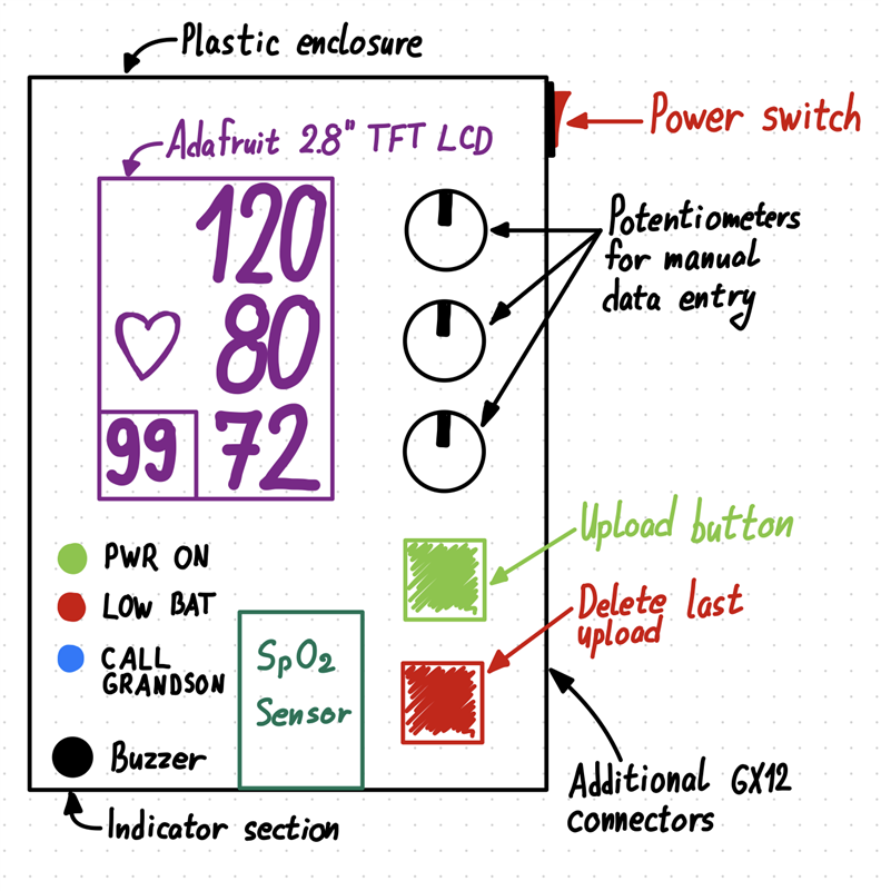
Most of the things actually stayed as shown in the picture above, but when we look at the schematic for the system design of the whole thing, I again made some changes, with the biggest one being already explained in the section above, about the HMS Mini.
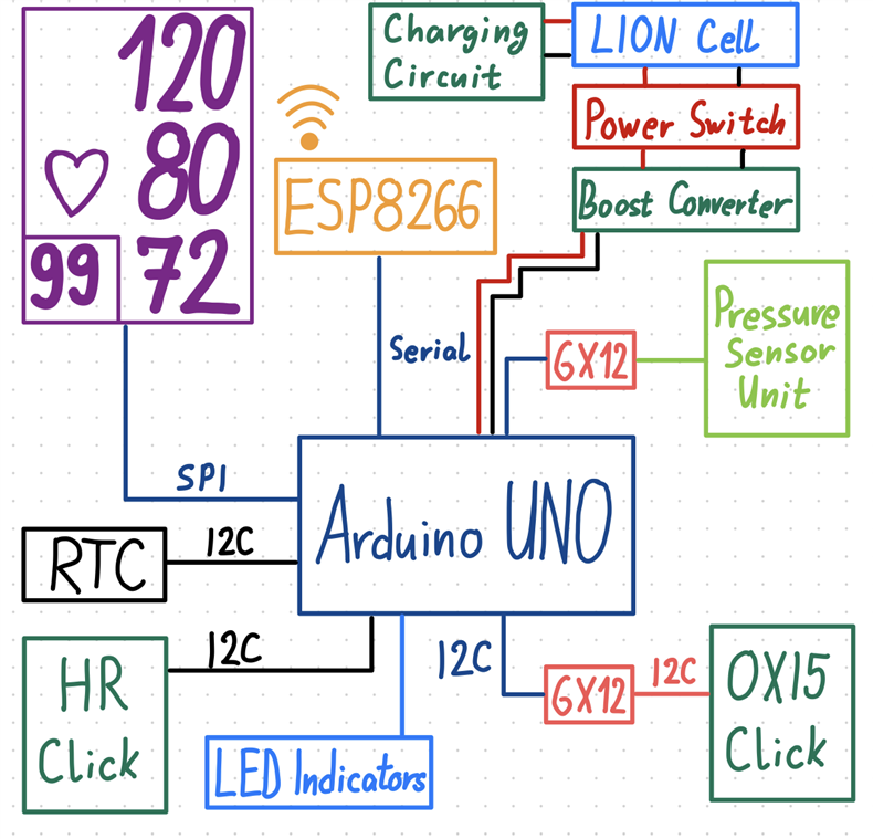
The change in question is that I didn't manage to get both of the heart sensors to work on the same Arduino, but that turned out great since now I have the HMS Mini as well! One thing that changed for the better is power electronics, where I found a great little board that combined everything needed for a 18650 cell with an included battery holder as I will show in the next section.
Electronics
There are 5 main components needed for the build. Most of them I've shown when I made my first prototype, but there's an additional, really cool one as well.
| {tabbedtable}City | Components |
|---|---|
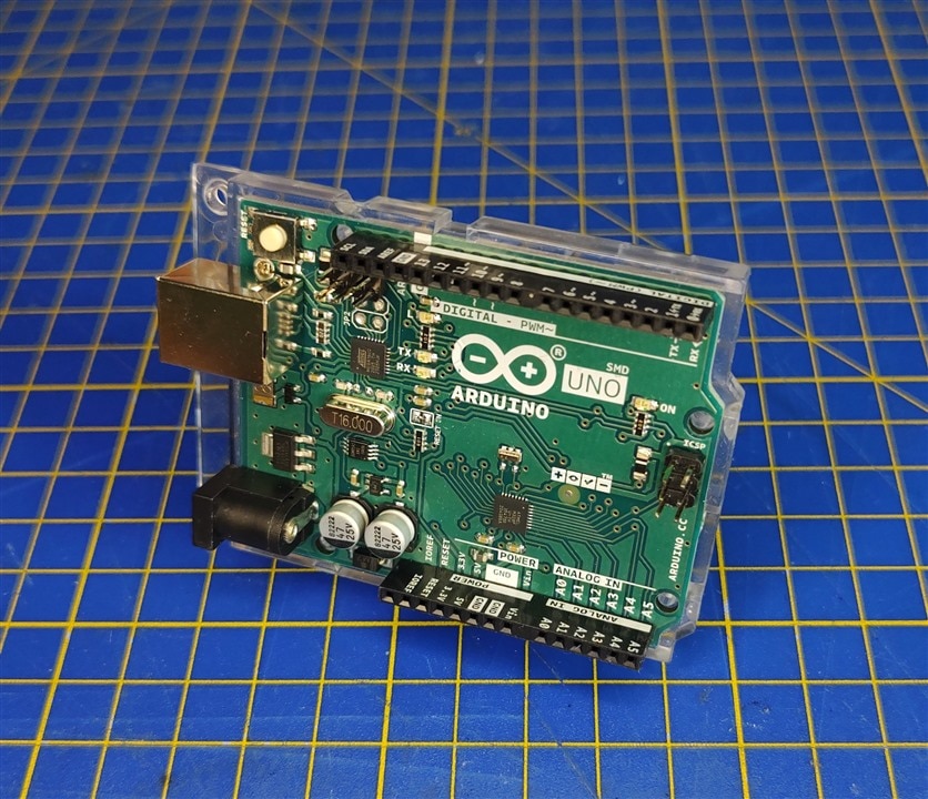
Arduino Uno |
As mentioned previously throughout my blogs, this is the component on which the whole project is based. This is also one of the components of the Starter Kit that I received as the challenger for this Design Challenge.
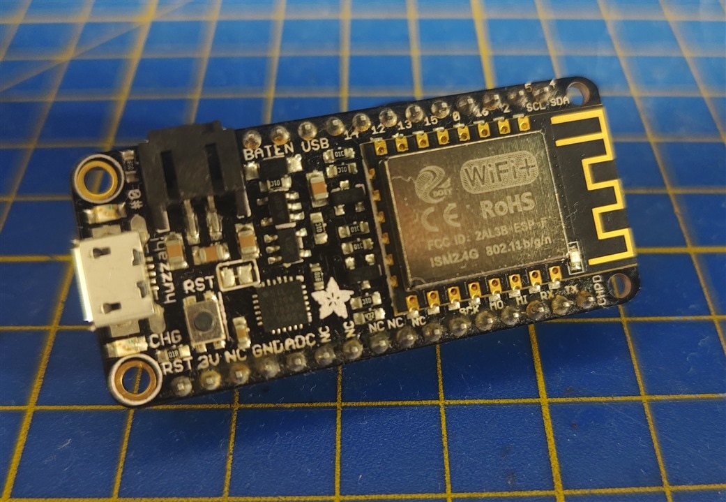
As mentioned already, it comes with the ATmega328P microcontroller and is the most recognizable Arduino out there! It doesn't have WiFi capabilities, and that's the reason why I'll be pairing it with an Adafruit Feather Huzzah (ESP8266) so I can connect my project to the internet. |
Adafruit Feather Huzzah |
As mentioned on the Arduino Uno tab, the next important component is the Adafruit Feather Huzzah. The Adafruit Feather Huzzah is an all-in-one ESP8266 WiFi development board with built-in USB and battery charging. It works on a 3.3V logic level so we need to be careful when using it with the Arduino Uno since the Arduino Uno is on a 5V logic level.
|
Heart Rate Click |
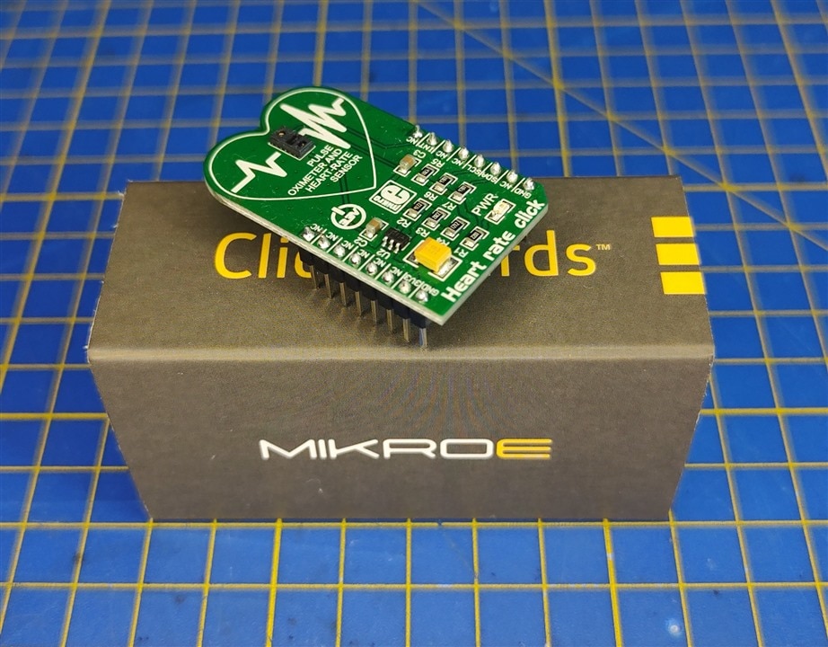
The pulse and oxygen saturation sensor that I will be using for this part of the project is the Heart Rate click, this is the board that has the MAX30100 sensor on board. Heart Rate click is a heart rate monitoring and pulse oximetry measuring Click board. It features an advanced oximeter and heart rate monitoring sensor, which relies on two integrated LEDs, a photosensitive element, and a very accurate and advanced low-noise analog front end, to provide clean and accurate readings.
The easiest way to connect to it is using the Arduino Uno Click shield, but we can also connect it to the power and to the I2C bus since that is how it communicates with the microcontroller. We only the 3.3V power rail for it, we don't need the 5V. |
Adafruit TFT LCD Display |
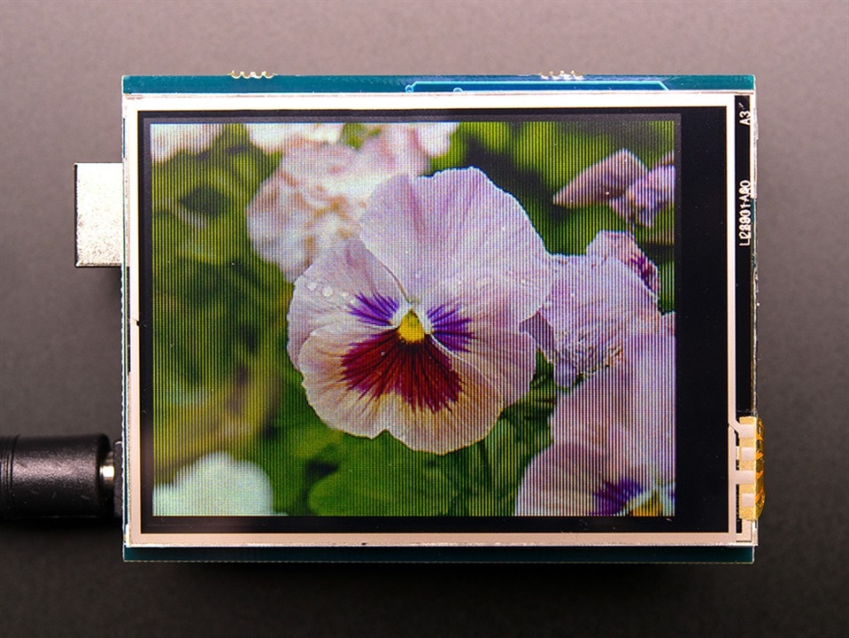
Adafruit 2.8" TFT Touch Shield for Arduino with Resistive Touch Screen is another Adafruit product I will be using for my project. I have the one with the resistive touch screen and it comes with a library which is incredibly easy to use. I don't need the touchscreen capabilities of the module, which is a good thing, since I managed to break mine while working on an older project. The display itself still works well though.
Picture from the Adafruit product page |
Powerbank Shield |
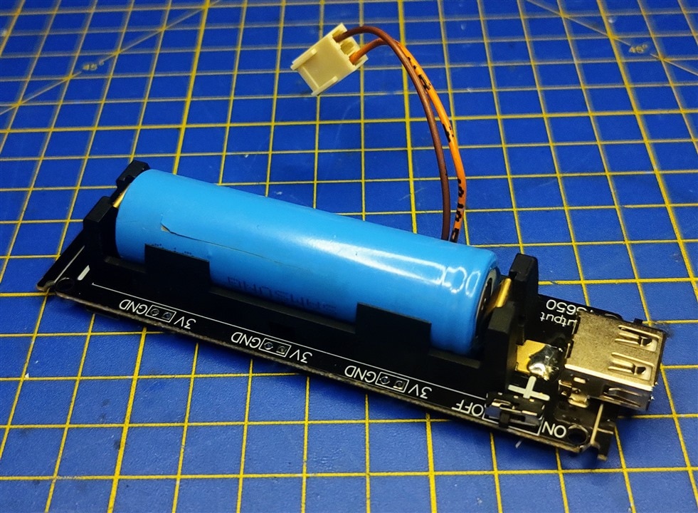
This is the new component I found for this build, and I love it. It's a power bank shield for a 18650 cell. It comes with a micro USB port for charging, and a USB A for charging your devices, but most importantly, it has pads on the sides that are either 5V or 3V to which we can solder. It really makes it a great all-in-one solution for portable projects and it can be used like a completely normal power bank if someone wants to.
|
Besides these components, I used a couple of buttons, potentiometers, resistors, and a lot of crimp nylon connectors. I love using them since they are incredibly cheap and really easy to use and crimp, though, I have a headache from time to time when a pin just pops out of the connector.
Final Schematic
The final schematic didn't change from the first prototype, except for a small addition, which in my opinion looks great, but it was incredibly tedious to solder.
The only thing that changed compared to the old schematic is that now I have 8 RED LED-s instead of just one that's shown in the picture above. And because I didn't want to burn out any pins on the Arduino, I needed a MOSFET power stage to power all of those LED-s. As to why there are 8 LED-s now, you will see them soon!
Soldering
Next on the list is soldering. This time, instead of 1 board that we need to solder, we need to solder 2 boards. One will be the main board, and the second one will be the LED board. I'll begin with the bigger and more complicated one.
Main Board
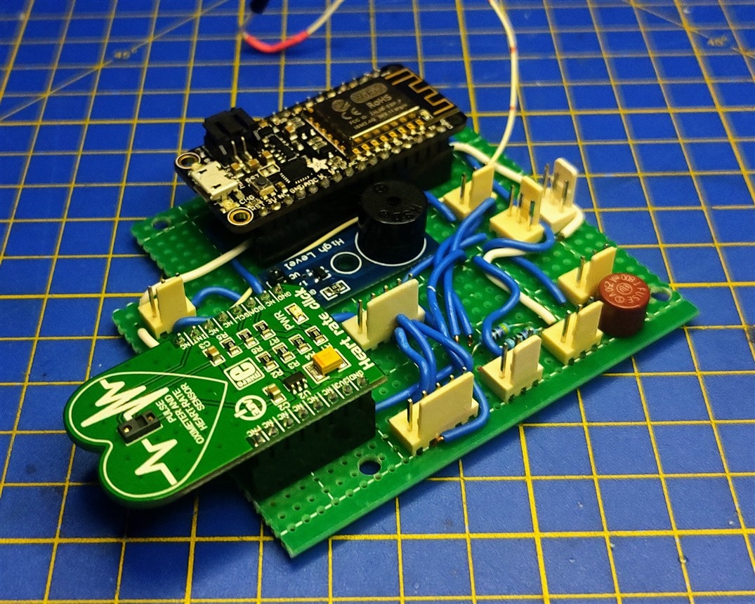
The main board in the HMS is like a motherboard in the computer, the main function of it is to connect everything together. Things like the buttons, potentiometers, and Arduino are all connected using connectors, while the things like the Adafruit Feather Huzzah and the MikroElektronika Heart rate Click have their own sockets on the main board. Here are a couple of pictures of the finished board.
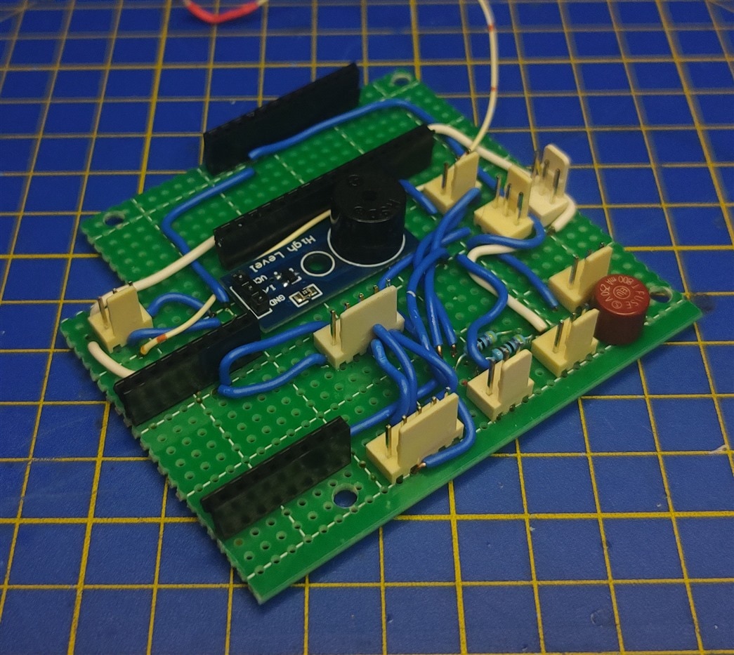
And here is a picture with the boards in their sockets.
Heart LED Board
The other board is actually a heart LED board. My initial idea was to have a heartbeat indicator either on the LCD or as a single LED as I've shown during testing the first prototype. But it got me thinking that it just looks plain and boring, so I decided to switch it up a bit and make a small heart shape out of 8 LED-s. The circuit to drive them is shown below, and only uses one MOSFET to do so.
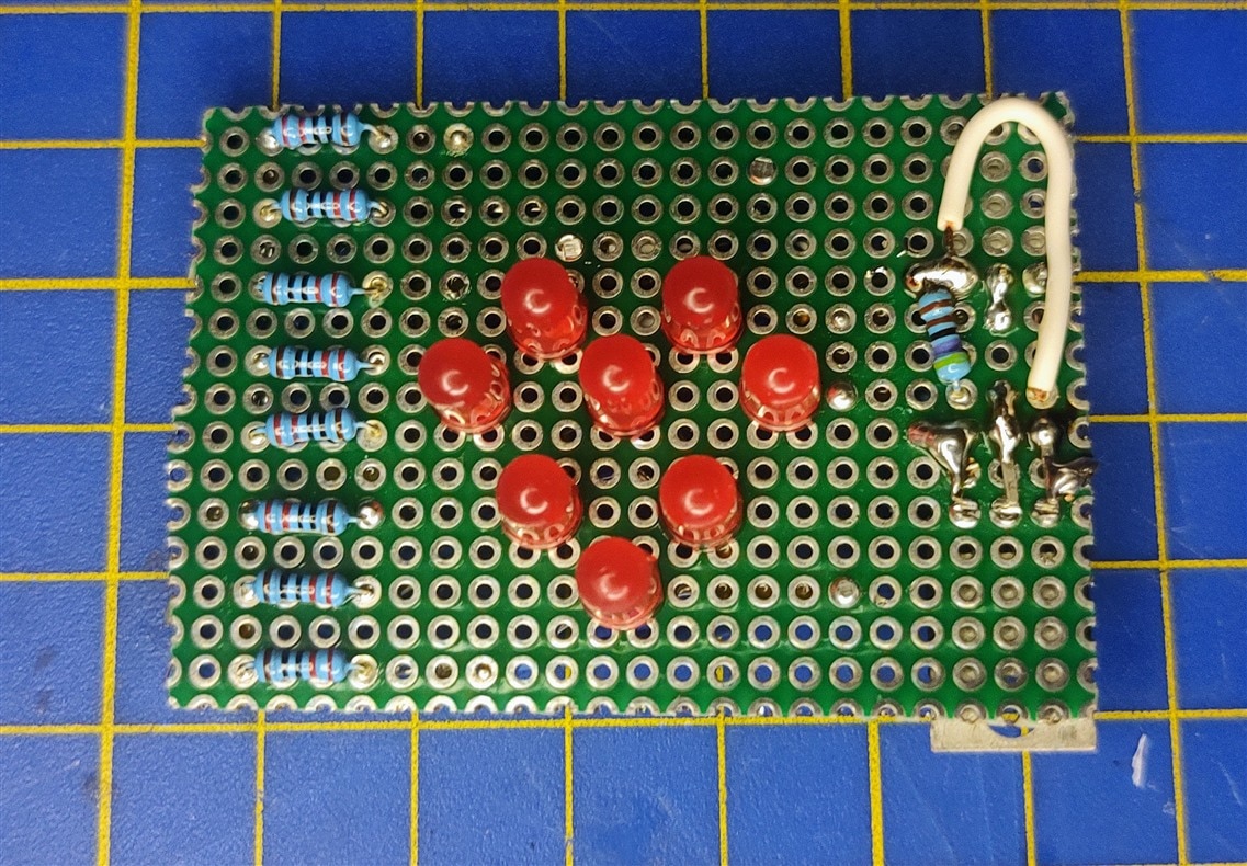
Because the LED-s needed to go up and through the LID, I had to keep all of the components as flush as possible with the perf board, hence why you only see resistors on top. It's a double-sided perf board, so I soldered on the connector and the MOSFET on the other side of the board.
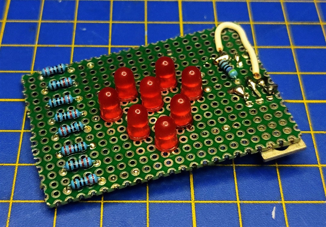
I am extremely happy with how it turned out, but as with the HMS Mini, the LED-s are incredibly bright. I got a small organized set of LED-s and just put 220Ohm resistors as I usually do with LED-s, but these are just incredibly bright. Still am thrilled with how it looks and the effect it gives.
Software
This is a topic I covered already with the first prototype and the software didn't change much from back then, except I also integrated the potentiometers. But that's where I ran into a little problem that I had to solve on the fly. For some reason, as soon as I would call the analogRead() function, the Heart Rate click would stop working for some reason. I didn't manage to find a reason why for now, so what I did to make it functional is use another button that I had added to the system. The system would start with the sensor doing its reading, and once the user presses and holds the red button, they can alter the blood pressure readings on the LCD. Here are the codes for both the Arduino and the Adafruit Feather Huzzah.
Arduino Code
#include "SPI.h"
#include "Adafruit_GFX.h"
#include "Adafruit_ILI9341.h"
#include "Wire.h"
#include "MAX30100_PulseOximeter.h"

// Pin definitions
#define TFT_DC 9
#define TFT_CS 10
#define PIN_LED_HR 6
#define PIN_LED_OXI 7
#define PIN_BUZZ 5
#define PIN_UPLOAD_BTN 3
#define PIN_RED_BTN 2

// Constants
#define REPORTING_PERIOD_MS     1000
#define READING_PERIOD_MS     50
#define SIGNAL_MS 70

// MQTT
String mqtt_hr_click = "measurement/hr_click";

volatile int hb1 = 0;
volatile int hb2 = 0;
volatile int spo21 = 0;
volatile int spo22 = 0;

volatile bool LED_HR = false;
volatile long LED_HR_time = 0;

volatile bool LED_OXI = false;
volatile long LED_OXI_time = 0;

volatile int hb_upload = 0;
volatile int spo2_upload = 0;

uint32_t tsLastReport = 0;
uint32_t tsLastPotRead = 0;

int systolic = 120;
int diastolic = 80;
int pulse = 60;
int new_s, new_d, new_p;

// Use hardware SPI (on Uno, #13, #12, #11) and the above for CS/DC
Adafruit_ILI9341 tft = Adafruit_ILI9341(TFT_CS, TFT_DC);

// Heart rate click
PulseOximeter pox;


// Callback (registered below) fired when a pulse is detected
void onBeatDetected()
{
    //Serial.println("Beat!");
    LED_HR = true;
    LED_HR_time = millis();
    hb_upload = hb1;
    spo2_upload = spo21;
}

void setup() {
  // Serial setup
  Serial.begin(9600);

  //
  //  PINS
  //
  pinMode(PIN_LED_HR, OUTPUT);
  pinMode(PIN_LED_OXI, OUTPUT);
  pinMode(PIN_BUZZ, OUTPUT);
  pinMode(PIN_UPLOAD_BTN, INPUT);
  pinMode(PIN_RED_BTN, INPUT);

  //
  //  INTERRUPTS
  //
  attachInterrupt(digitalPinToInterrupt(PIN_UPLOAD_BTN), ButtonPress, RISING);


  //
  //  TFT LCD
  //

  tft.begin();
  tft.fillRect(0, 0, 240, 320, ILI9341_WHITE);
  tft.setTextColor(ILI9341_BLACK);

  tft.setTextSize(10);
  tft.setCursor(10, 10);
  tft.print(String(systolic));

  tft.setCursor(10, 90);
  tft.print(String(diastolic));

  tft.setCursor(10, 170);
  tft.print(String(pulse));

  tft.setTextSize(6);
  tft.setCursor(10, 260);
  tft.print(hb_upload);

  tft.setCursor(120, 260);
  tft.print(spo2_upload);


  //
  //  HR CLICK
  //

  //Serial.print("Initializing pulse oximeter..");
  // Initialize the PulseOximeter instance
  // Failures are generally due to an improper I2C wiring, missing power supply
  // or wrong target chip
  if (!pox.begin()) {
      //Serial.println("FAILED");
      for(;;);
  } else {
      //Serial.println("SUCCESS");
  }

  // The default current for the IR LED is 50mA and it could be changed
  //   by uncommenting the following line. Check MAX30100_Registers.h for all the
  //   available options.
  // pox.setIRLedCurrent(MAX30100_LED_CURR_7_6MA);

  // Register a callback for the beat detection
  pox.setOnBeatDetectedCallback(onBeatDetected);

}

void UpdateHR(){

  tft.fillRect(0, 260, 130, 100, ILI9341_WHITE);

  tft.setTextSize(5);
  tft.setCursor(10, 260);
  tft.print(hb_upload);

  tft.fillRect(120, 260, 130, 100, ILI9341_WHITE);
  tft.setCursor(120, 260);
  tft.print(spo2_upload);
}

void UpdateSystolic()
{
  tft.fillRect(0, 0, 240, 90, ILI9341_WHITE);
  tft.setTextColor(ILI9341_BLACK);
  tft.setTextSize(10);
  tft.setCursor(10, 10);
  tft.print(String(systolic));
}

void UpdateDiastolic()
{
  tft.fillRect(0, 90, 240, 80, ILI9341_WHITE);
  tft.setTextColor(ILI9341_BLACK);
  tft.setTextSize(10);
  tft.setCursor(10, 90);
  tft.print(String(diastolic));
}

void UpdatePulse()
{
  tft.fillRect(0, 170, 240, 80, ILI9341_WHITE);
  tft.setTextColor(ILI9341_BLACK);
  tft.setTextSize(10);
  tft.setCursor(10, 170);
  tft.print(String(pulse));
}

void ButtonPress(){
  delay(100);
  if(digitalRead(PIN_UPLOAD_BTN) == HIGH){
    //String msg = MQTT_HR_CLICK + DIVIDER + "Heart rate: " + String(hb_upload) + "BPM SpO2: " + String(spo2_upload) + "%";
    String bp_msg = String(systolic) + "/" + String(diastolic) + "/" + String(pulse);
    Serial.println(mqtt_hr_click + "&" + "Heart rate: " + String(hb_upload) + "BPM, SpO2: " + String(spo2_upload) + "%, Blood Pressure: " + bp_msg);
  }
}


void loop() {

  if(digitalRead(PIN_RED_BTN) == LOW)
  {
    // Updating the Heart rate click
    pox.update();

    if(millis() - tsLastReport > REPORTING_PERIOD_MS)
    {
      /*
      Serial.print("Heart rate:");
      Serial.print(pox.getHeartRate());
      Serial.print("bpm / SpO2:");
      Serial.print(pox.getSpO2());
      Serial.println("%");
      */
      hb1 = pox.getHeartRate();
      spo21 = pox.getSpO2();
      UpdateHR();

      tsLastReport = millis();
      //UpdateOxi();
    }

    // LED Heart rate Click
    if(LED_HR == true)
    {
      digitalWrite(PIN_LED_HR, HIGH);
      digitalWrite(PIN_BUZZ, HIGH);
      if(millis() - LED_HR_time > SIGNAL_MS)
      {
        digitalWrite(PIN_LED_HR, LOW);
        digitalWrite(PIN_BUZZ, LOW);
        UpdateHR();
        LED_HR = false;
      }
    }
  }
  else
  {
    // Update potentiometers
    if(millis() - tsLastPotRead > READING_PERIOD_MS)
    {

      new_s = map(analogRead(A3), 1023, 0, 80, 200);
      new_d = map(analogRead(A2), 1023, 0, 40, 140);
      new_p = map(analogRead(A1), 1023, 0, 40, 140);

      if(new_s != systolic)
      {
        systolic = new_s;
        UpdateSystolic();
      }
      if(new_d != diastolic)
      {
        diastolic = new_d;
        UpdateDiastolic();
      }
      if(new_p != pulse)
      {
        pulse = new_p;
        UpdatePulse();
      }

      tsLastPotRead = millis();
    }
  }

}
Adafruit Feather Huzzah Code
#include <ESP8266WiFi.h>
#include <PubSubClient.h>

// Change the credentials below, so your ESP8266 connects to your router
const char* ssid = "SSID";
const char* password = "PASSWORD";

// Change the variable to your Raspberry Pi IP address, so it connects to your MQTT broker
const char* mqtt_server = "SERVER_IP";

// Initializes the espClient. You should change the espClient name if you have multiple ESPs running in your home automation system
WiFiClient espClient;
PubSubClient client(espClient);

bool stringComplete = false;
String inputString = "";
String topic = "";
String data = "";


// Don't change the function below. This functions connects your ESP8266 to your router
void setup_wifi() {
  delay(10);
  // We start by connecting to a WiFi network
  Serial.println();
  Serial.print("Connecting to ");
  Serial.println(ssid);
  WiFi.begin(ssid, password);
  while (WiFi.status() != WL_CONNECTED) {
    delay(500);
    Serial.print(".");
  }
  Serial.println("");
  Serial.print("WiFi connected - ESP IP address: ");
  Serial.println(WiFi.localIP());
}

// This functions reconnects your ESP8266 to your MQTT broker
// Change the function below if you want to subscribe to more topics with your ESP8266
void reconnect() {
  // Loop until we're reconnected
  while (!client.connected()) {
    Serial.print("Attempting MQTT connection...");
    // Attempt to connect
    /*
     YOU MIGHT NEED TO CHANGE THIS LINE, IF YOU'RE HAVING PROBLEMS WITH MQTT MULTIPLE CONNECTIONS
     To change the ESP device ID, you will have to give a new name to the ESP8266.
     Here's how it looks:
       if (client.connect("ESP8266Client")) {
     You can do it like this:
       if (client.connect("ESP1_Office")) {
     Then, for the other ESP:
       if (client.connect("ESP2_Garage")) {
      That should solve your MQTT multiple connections problem
    */
    if (client.connect("ESP8266Client")) {
      Serial.println("connected");
      // Subscribe or resubscribe to a topic
      // You can subscribe to more topics (to control more LEDs in this example)
      client.subscribe("room/lamp");
    } else {
      Serial.print("failed, rc=");
      Serial.print(client.state());
      Serial.println(" try again in 5 seconds");
      // Wait 5 seconds before retrying
      delay(5000);
    }
  }
}

void setup() {
  // put your setup code here, to run once:
  Serial.begin(9600);
  setup_wifi();
  client.setServer(mqtt_server, 1883);
}

void loop() {
  // put your main code here, to run repeatedly:
  if (!client.connected()) {
    reconnect();
  }
  if(!client.loop())
    client.connect("ESP8266Client");

  if(stringComplete){
    if(inputString.indexOf("&") != -1){
      topic = inputString.substring(0, inputString.indexOf("&"));
      data = inputString.substring(inputString.indexOf("&") + 1);
      Serial.print("Topic: ");
      Serial.println(topic);
      Serial.print("Data: ");
      Serial.println(data);
      Serial.println("Publishing....");
      client.publish((char*) topic.c_str(), (char*) data.c_str());
      Serial.println("Done publishing");
    }
    inputString = "";
    stringComplete = false;
  }

}

/*
  SerialEvent occurs whenever a new data comes in the hardware serial RX. This
  routine is run between each time loop() runs, so using delay inside loop can
  delay response. Multiple bytes of data may be available.
*/
void serialEvent() {
  while (Serial.available()) {
    // get the new byte:
    char inChar = (char)Serial.read();
    // add it to the inputString:
    inputString += inChar;
    // if the incoming character is a newline, set a flag so the main loop can
    // do something about it:
    if (inChar == '\n') {
      stringComplete = true;
    }
  }
}
Build
Before we get to testing, there is only one thing left, and that is to assemble everything together. As I've already mentioned above, all of the 3D models that you see in this section will be posted to GitHub pretty soon so you can download them for free to print out. The link to the GitHub page will be in the comments once it's all set up.
Enclosure and 3D Prints
I used an off-the-shelf enclosure for this build, but not a Hammond one as I did for the HMS Mini. As for the 3D printing, I had to print out 3 different things for everything to come together. The first thing is the electronics mount. This is something that I got used to doing anytime I need to pack a lot of electronics in a small area. It can be done rather quickly if you the board sizes and it prints really fast.
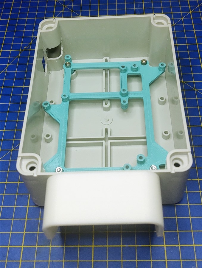
On the front, in the picture above, you can also see the shroud around the sensor. Its purpose is to block out a bit of the light coming from the surroundings as well as protect the sensor in case of a fall. Another thing I had to print also was the mount of the LED heart. It was pretty easy to model, since the LED-s are 5mm in diameter, and the spacing between them is easy to figure out since they are on a perf board with 2.54m spacing between adjacent holes.
Final Assembly
And again, all we need to do before testing is to assemble everything. I had to modify the enclosure a bit so the Arduino USB port can go through as well as the Heart Rate Click board with the sensor part. You can see all of the modules fitting snuggly next to each other.
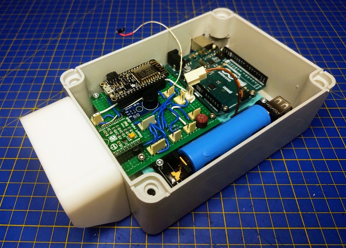
Another thing that required a fair amount of assembly and soldering was the lid of the box as well. We need to wire up the 2 buttons, the power switch, 3 potentiometers, an LED heart board, and a TFT LCD.
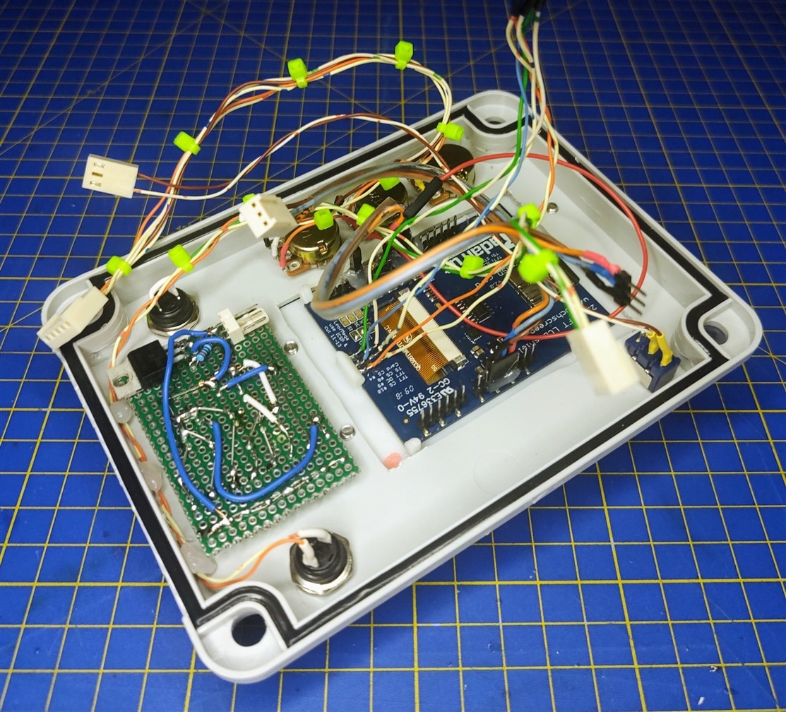
I made a few cables using the nylon connectors and slowly crimped them making sure that there is enough length to the cables.
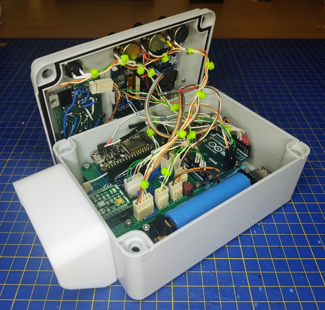
All that's left now is to close the lid and secure it with 4 screws, and we have the finished HMS! One thing I would just like to mention, you can see the 3D printed white mount around the LCD, but I didn't mention it in the 3D printing section, and the reason for that is because the model is just bad simply said and I don't have a better one. It's the reason I cracked this display in the first case.
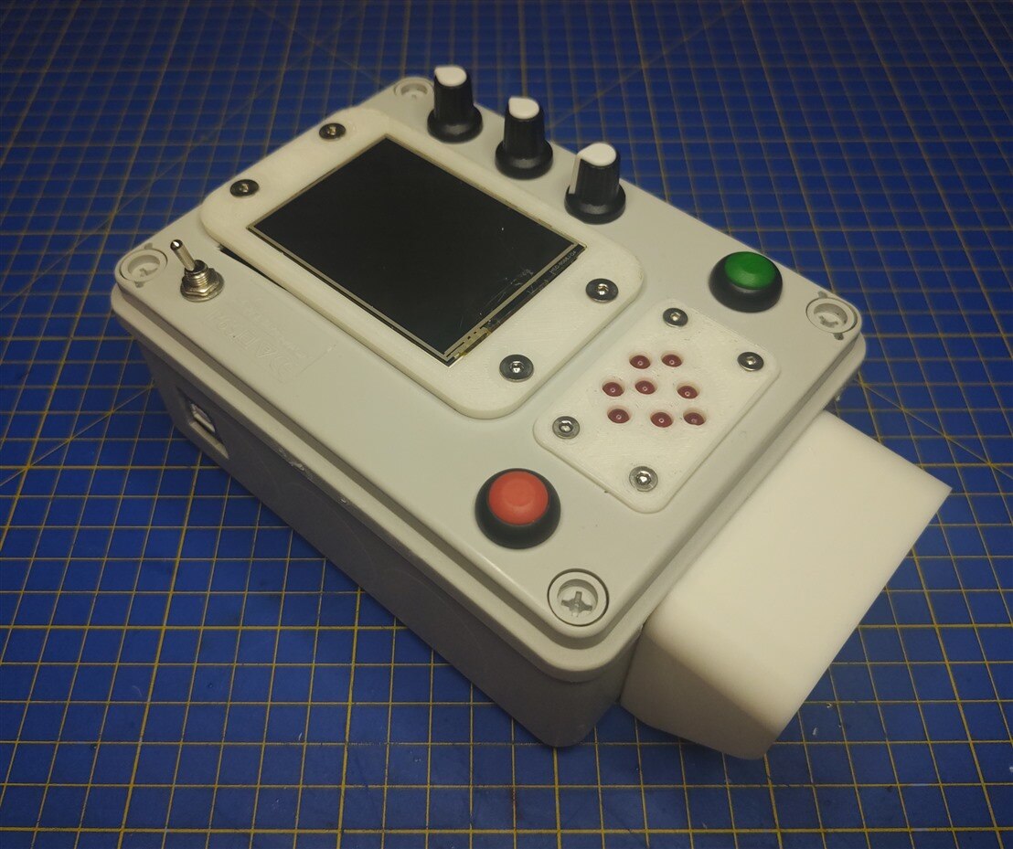
With that, the assembly is finished!
Testing
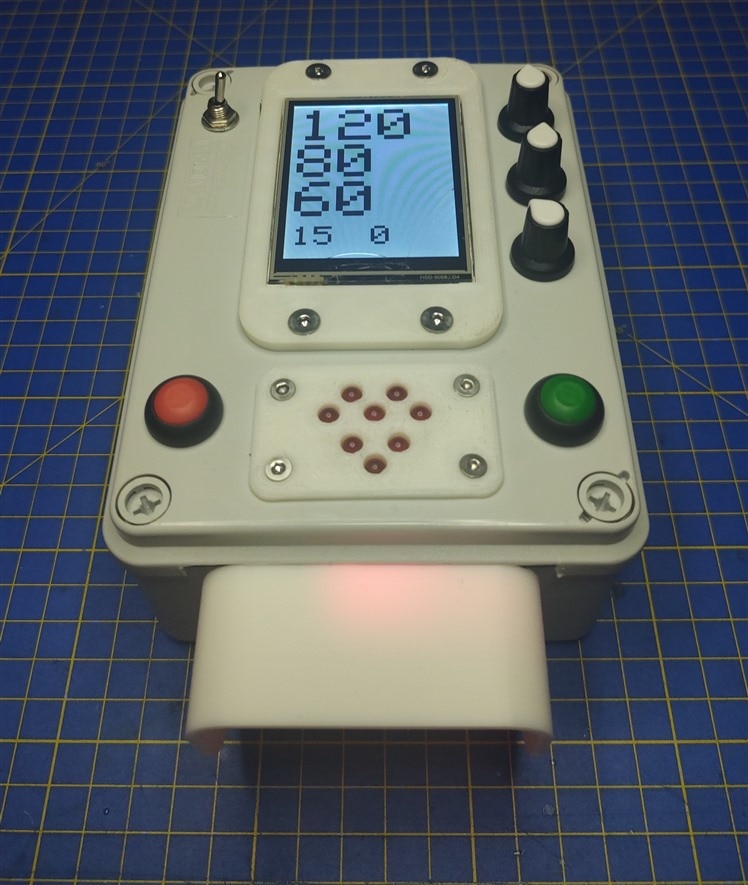
This part is always so rewarding after all of the necessary stages that came before it. Before I show the video, I want to explain how this device is intended to be used. First, we power it on using the power switch next to the LCD. After powering on, we can put our finger on the sensor in the front and look at the readings from the sensor at the bottom of the LCD screen. Every time the sensor detects a heartbeat, we will get a buzzer sound, as well as a flash from the Heart, shaped LED pulse indicator in the front. If now you want to enter the blood pressure you measured on a commercial device, you hold down the Red button, and while holding it, you turn the potentiometers to adjust the numbers on the screen to match the values from the commercial unit. Once you're done with that, you can press the green button, and the HMS will upload that data to the server which will then push notifications to a laptop or mobile phone.
And it works! There was some troubleshooting needed with a broken connector, but I got it working rather quickly. I'm sad that the pressure sensor approach didn't give any useful results for now, but this alternative is rather simple to use as well. To end with the HMS, here is a picture of it working!
4. Guest Star!
Before I end this blog with a summary of my whole project for this competition, I have a guest star who volunteered to test out the HMS and the HMS Mini, my lovely grandma! As I've been talking from the start, my idea from the beginning was to design a device that could help her when she needs to take her measurements, and also make it easier for her to inform us of her measurements, when she is home alone. That's one of the reasons why I constantly tried making the interfaces of these devices as intuitive as possible because, for something that she could actually use, there's no point in a device with wires going on all sides and needing a Serial Monitor to read the data. Let's begin with her testing the HMS Mini!
HMS Mini Test
She was incredibly excited when I asked her if she wanted to try out the devices that I made. She is pretty good with her phone and loves watching recipes on YouTube, so the HMS Mini was a real breeze to use for her. I'm sad I couldn't get an audio of the heartbeat from the Oxi5 Click, but it's still providing the BPM and the SpO2 level. Next up is the HMS!
HMS Test
To keep the video shorter, you can see the commercial blood pressure monitor on the table which she used to get her readings, and now all she needed to do was enter those readings into the HMS and send it to my phone. The Heart Rate Click part was exactly the same as with the Oxi5 on the HMS Mini, so there weren't any problems there, and while she doesn't have a problem with turning potentiometers, they were a bit too sensitive for both mine and hers taste. But on the other side, a 10-turn potentiometer would be a bit too much as well, maybe an encoder would be a better option? Of course, the ideal option would be to have the pressure sensor and automate everything, but sadly I still have work to do on that.
Testing Conclusion
While the potentiometers really aren't an ideal solution, I'm extremely happy with how both of these turned out, both the HMS Mini and the HMS. The pressure sensor feature is something I will continue to work on after this competition in hopes of actually getting accurate readings from it. I am also extremely happy to say that the guest star was thrilled to try out both of the devices and to feature in the videos! So I would love to give a big thanks to my grandma! Both devices were a breeze to use, especially the HMS Mini since its interface is a lot simpler compared to the HMS. I will be keeping the HMS mini somewhere around the living room, while I continue working on the HMS and the pressure sensor feature.
5. Summary
This will be a summary not just for this blog but generally for the whole project for this competition. I'll start from the beginning and my idea for this project. My idea for this design challenge is to design a small Health Monitoring System for my grandma, hence, why the name HMS for this project. My end goal is to have a user-friendly device for my grandma, that can do data logging for all of her measurements, as well as be an easy way to check her blood oxygen saturation as well as check if there is an irregular heartbeat. To summarize everything, I'll put everything into a requirements list that I wish to fulfill with this project.
Requirements list:
- Blood oxygen monitoring
- Heartbeat buzzer
- Heart rate measurement
- Data logging everything to a microSD
- Data analysis and presentation - This is something I would do to extract all of the data before she goes to the doctor, idea is to automize this as much as possible and have a ready-to-go report for the doctor
- User-friendly interface
- RTC for accurate time tracking
- Ability to manually enter blood pressure measurements
- Arduino-based blood pressure monitor using a pressure sensor
That was the requirement list I wrote down when I started, and while I didn't fulfill all of the goals, I'm still happy with how far I got, and I'm declaring it as a success, cause, in the end, I ended up with 2 function devices, both with its upsides and downsides. Through the blogs, I went and covered my whole thought process for this project, from the system design.
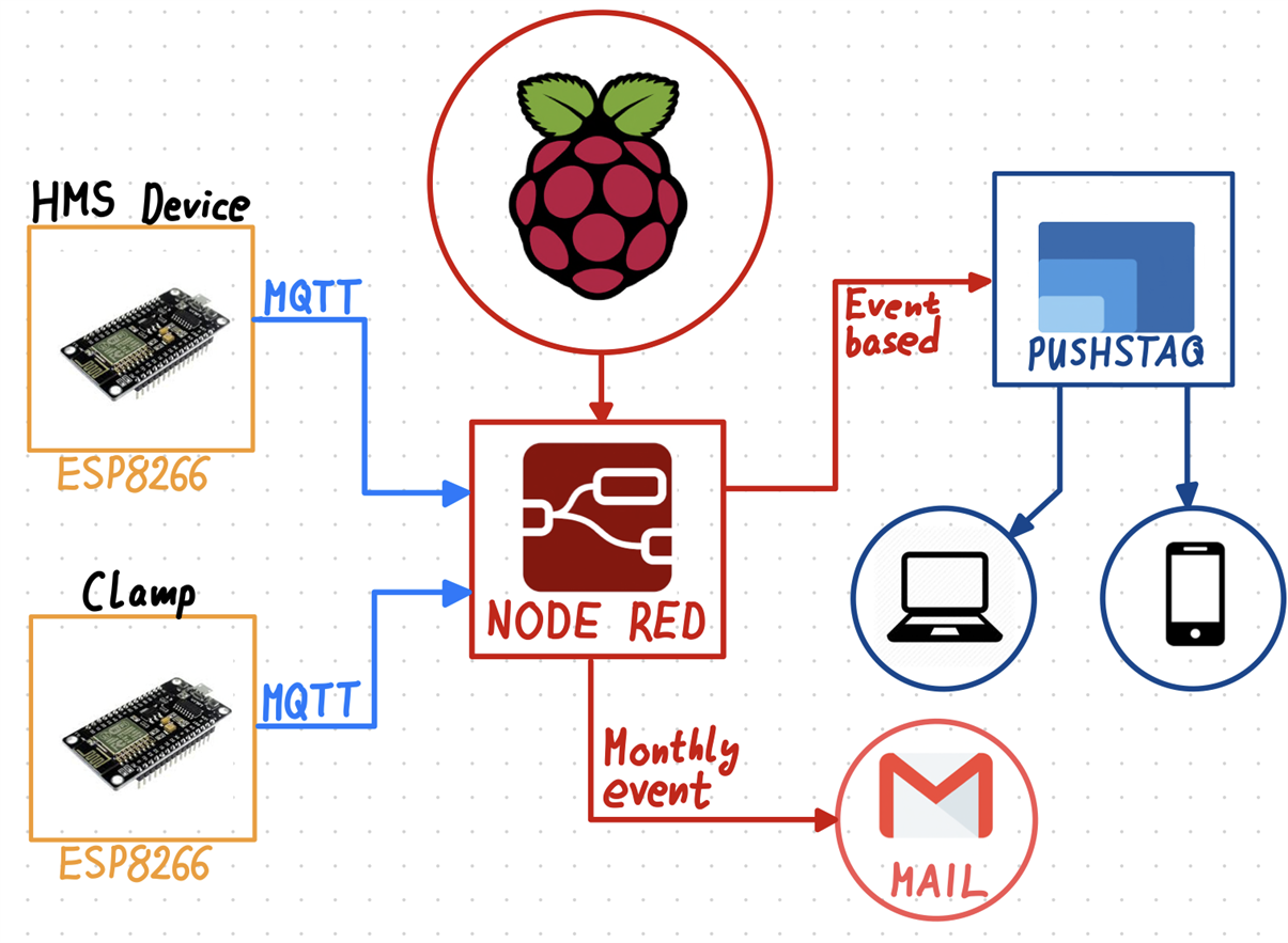
For individual device design where I went into all of the details about both electronics and software.
I've also covered the whole process of setting up a Raspberry Pi server from zero running Node-Red and how I used that to push notifications to my phone.
While I didn't succeed in getting the blood pressure reading from the pressure sensor, I still managed to get and extract a lot of data from it as you can see from some of the pictures below.
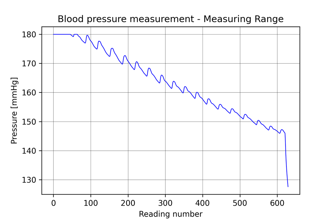
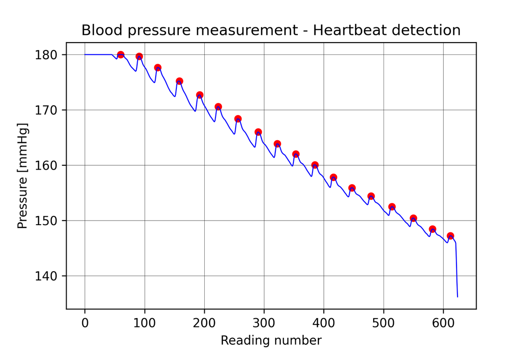
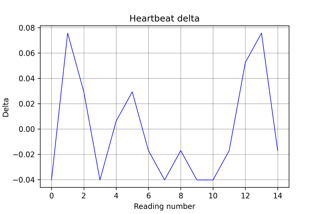
In the end, I finished with 2 pretty cool little devices, that my grandma had no trouble using.
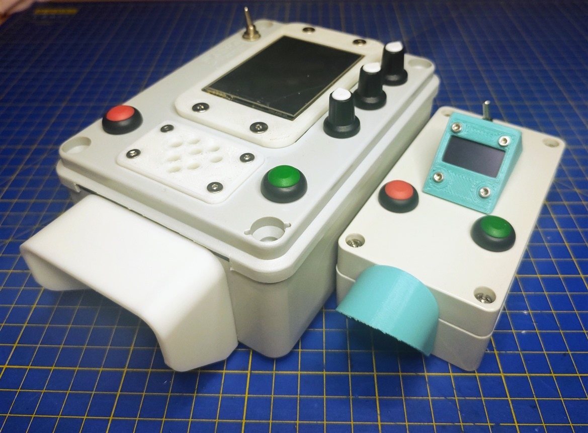
This was a really fun design challenge, I had a blast the last few weeks trying to get everything to work. I want to thank again the judges for the opportunity to be one of the sponsored challengers for this competition. It was really rewarding when I saw grandma using both devices without any hassle after trying to figure out the simplest and most optimal interface for them. I'm extremely happy with how the whole project/competition went, I would have only loved more time to play around with the pressure sensor so I can get it to work. I would also like to thank my grandma for helping with the feedback as I was working on this since this was being designed for her after all. I uploaded a PDF with all of the sketches I made during the competition! Thanks for reading the blog, hope you like it!
Previous blogs:
- Blog #1 - Introduction
- Blog #2 - System Design
- Blog #3 - First Prototype
- Blog #4 - Measuring Blood Pressure
Milos


