


Table of Contents
Introduction
This is my 8th blog in a series I am writing for the Summer of Sensors Design Challenge kindly sponsored by Element14 in partnership with Vishay. The challenge is to make use of two selected sensor boards from Vishay’s SensorXplorer range. In previous blogs I documented the design and development of the electronics and software elements of my project - an adaptive, smart bulb controller. Today I will be showing you the design, build and assembly of the 3D printed case/box/enclosure.
Building the CAD Model
The easiest way to showcase this part of the project is using a video, so please sit back and enjoy the wonder that is 3D CAD. For reasons explained in the following demonstration, I will be using the free online CAD editor onshape.com:
3D Printing the Model
Having designed all the parts of the 3D model and "assembled" them together in the CAD package to make sure that all the sensors would physically fit and operate where I wanted them to go, the next stage was to get the parts 3D printed. Sadly my 3D printer is offline for repair and modification at the moment, but fortunately one of my friends who is into his 3D printing kindly agreed to pop my model into his 3D printer for me - thanks a million!
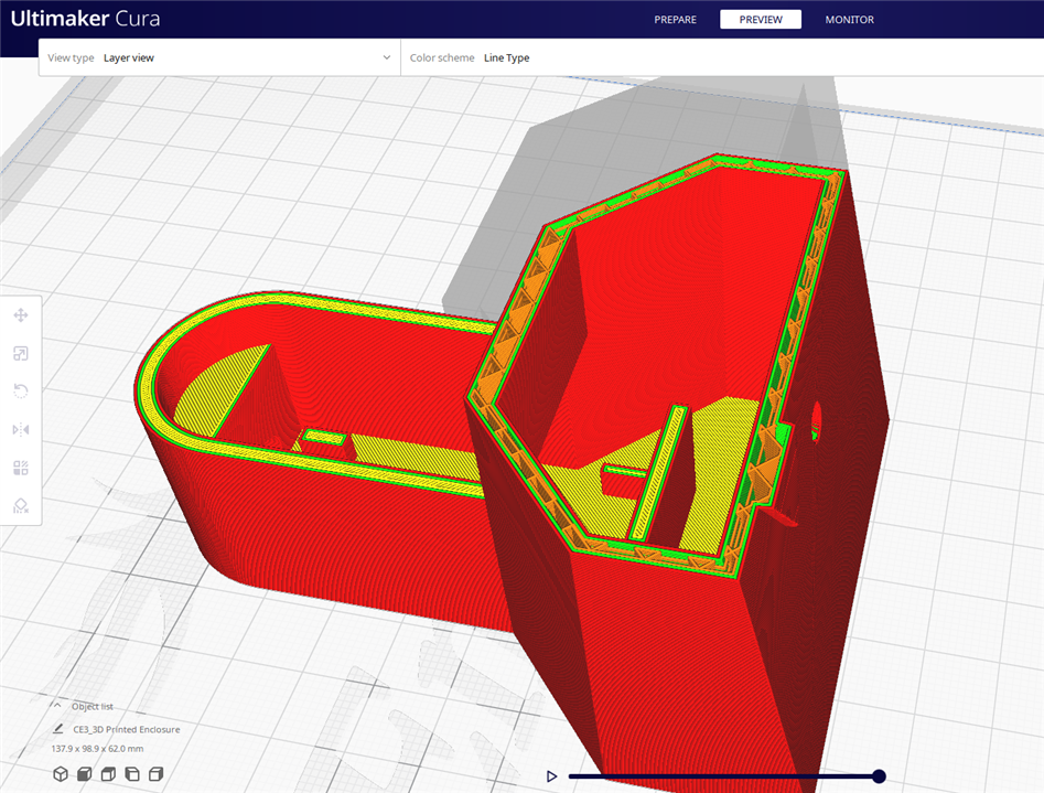
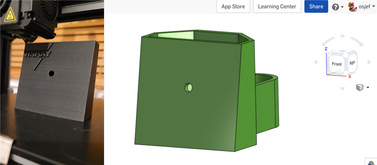
After exporting the model in STL format from the onshape editor, the model is first put through the 3D printer's slicing software - in this case "Cura". Below you can see a cross-sectional view of the 3D model prior to printing:
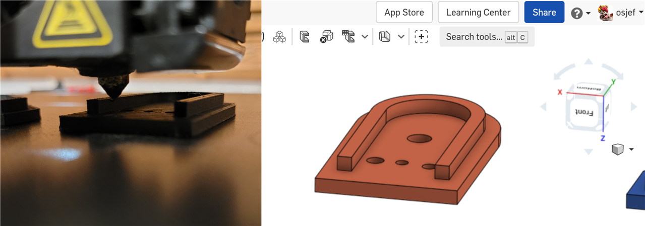
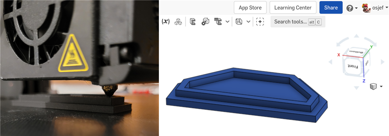
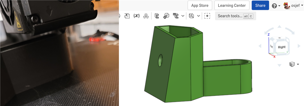
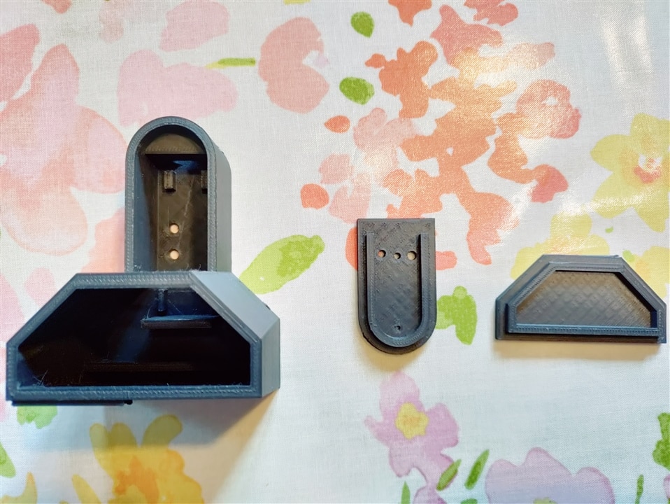
And here are a few pictures of the parts being printed alongside their 3D design:
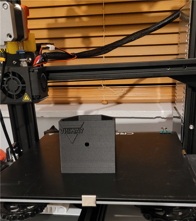
And here is the final 3D printed box, ready to be removed from the build platform. (Note that the "Vishay" logo is absent from this CAD model as it was added to the model in Cura.)
Assembling the Project
With everything 3D printed, the next stage is the assembly:
- Fixing the ESP32 micro-controller board (inverted) into the bottom of the box
- Soldering the VEML3328 sensor board to the single-sided copper stripboard along with the two I2C pull-up resistors
- Placing that assembly into the lower section at the back of the box
- Sliding the VCNL4035 sensor board vertically into the front of the box
- Soldering the last wires in place
- Putting the lids on
The model removed from the build platform
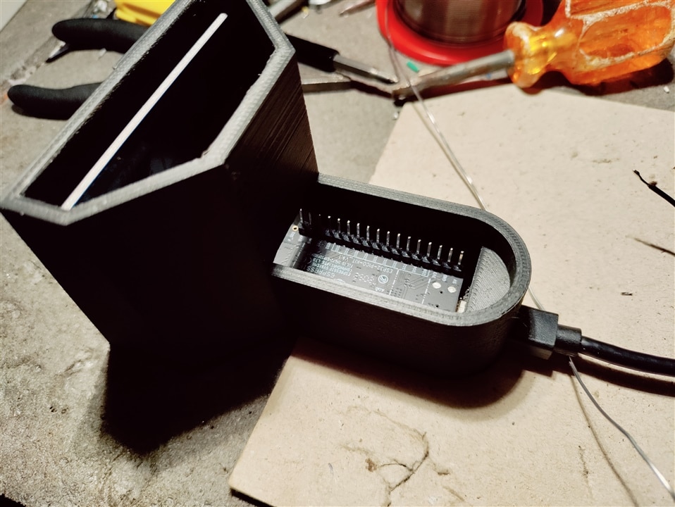
ESP32 micro-controller fitted (inverted to allow access to the reset button through the bottom of the box)
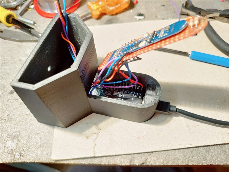
Soldering the VEML3328 sensor board connections
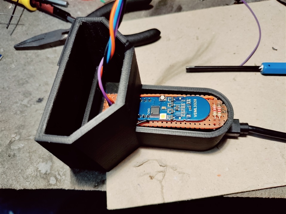
Fitting the VEML3328 sensor board in place (just about enough clearance!)
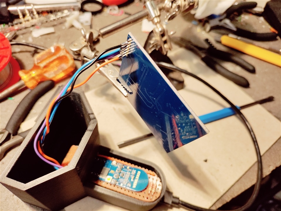
Soldering the VCNL4035 sensor board connections
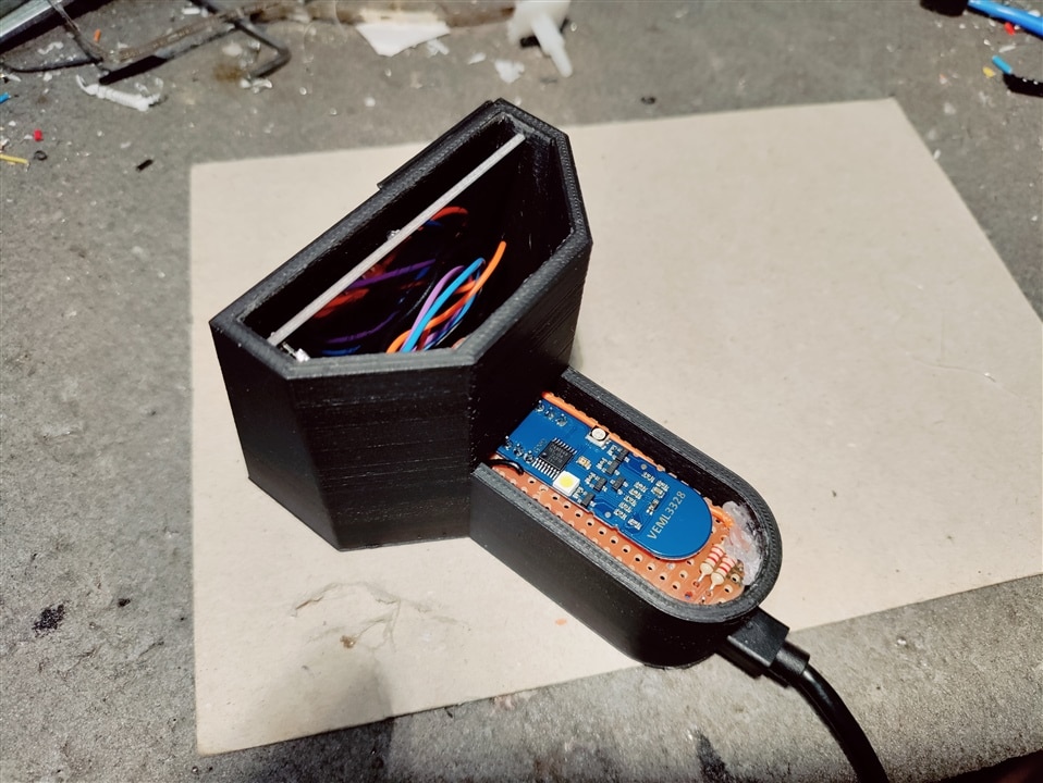
All sensor boards wired up and fitted - ready for the lids
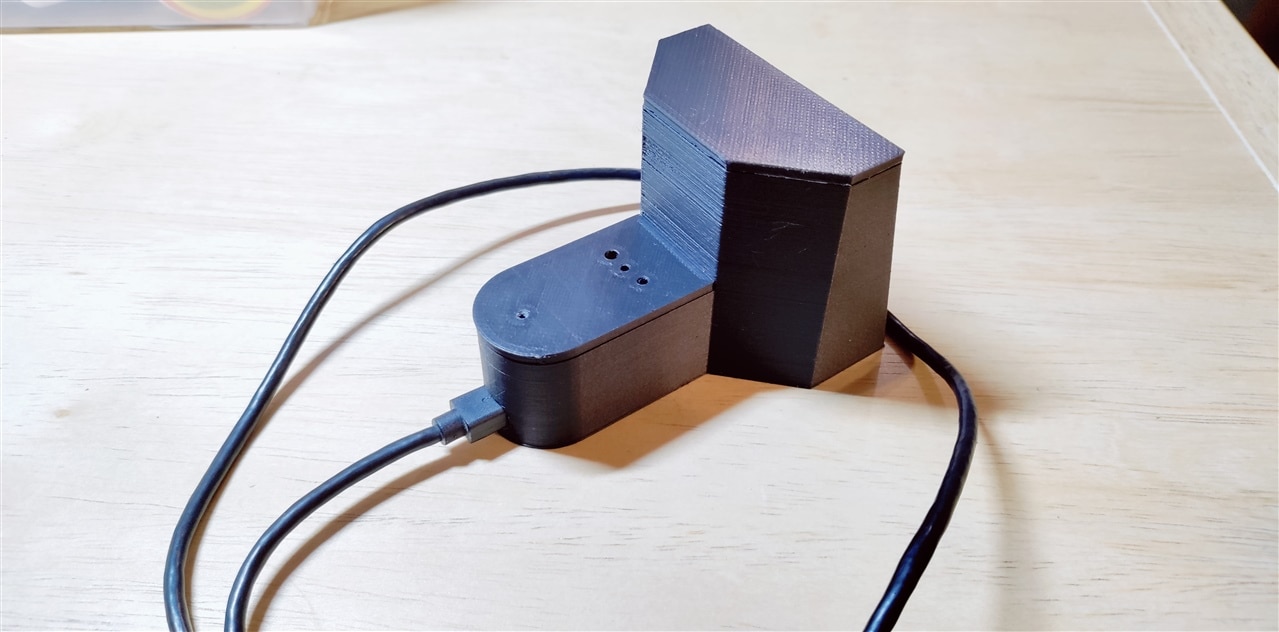
All assembled and USB cable fitted
Powering it Up
And the final step is to turn it on and hope it doesn't let out the magic smoke...
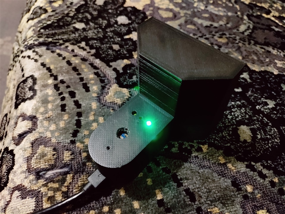
It worked! And the green LED (which aligns with the hole in the lid perfectly) is lit indicating a connection has been made with the smartbulb.
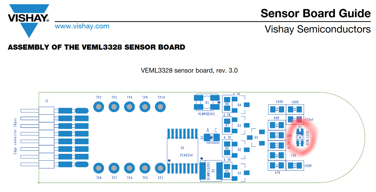
Those of you who are observant will have spotted that an extra hole has appeared in the lower lid  Well, when I was designing the lid I spotted a component on the board between the two LEDs which looked like the VEML3328 colour sensor. However, when I powered everything up with the lids fitted, it wasn't reading the colour of the room correctly (or at all in fact). After digging out the PCB layout for the VEML3328 sensor board I realised that the component in between the two LEDs is actually the IR LED (kind of makes sense now looking back on it - there is the RGB LED, the white LED and the IR LED all three in a row). Looking at the PCB layout I spotted that the VEML3328 colour sensor SMD component is actually at the tip of the board (the rounded end) - wonderful thing is the datasheet! The position of the sensor is highlighted in the PCB layout below:
So I manually drilled a hole into the lower lid, re-assembled and it magically sprung into life.
Coming Next...
- There were a few minor mods I had to make to the 3D printed box (e.g. the sensor position as mentioned above) so I'm going to make a few tweaks to the CAD model and print the final (hopefully perfect) case.
- After that I'm going to make a few tweaks to the software to "calibrate" the sensors. For example, to make sure the proximity sensor switches the bulb on and off at exactly the right distance (I don't want it turning off whilst in the middle of reading my book).
- And finally I have spotted that there is a pin marked INT on the gesture board. After looking at the datasheet, this is an output interrupt pin which can be configured to go logic high under certain conditions (based on the proximity sensor or the ambient light sensor). Now there is an interrupt input on the ESP32 which can be used to wake it up out of sleep mode, so my plan for an additional enhancement, if I have enough time, is to connect this INT pin to the ESP32 and get the gesture board to wake up the ESP32 from its power saving mode based on the distance to the proximity sensor. This way, the ESP32 can be sleeping most of the time (hence saving power) and then when I sit down on my chair the interrupt will trigger the ESP to wake up and then it will do all its clever control of the smartbulb until I get up from the chair at which point the ESP will turn off the light bulb and enter its sleep mode - waiting for its next interrupt.
Many thanks for taking the time to read this blog. We are virtually there now, so please stay tuned for one more blog with the final finishing touches.
| Previous Blog (Part 7) | Next Blog (Part 9) |
-

osjef
-
Cancel
-
Vote Up
0
Vote Down
-
-
Sign in to reply
-
More
-
Cancel
Comment-

osjef
-
Cancel
-
Vote Up
0
Vote Down
-
-
Sign in to reply
-
More
-
Cancel
Children