


Table of Contents
Introduction
Welcome to my 9th and final blog, and what a journey it’s been! Back in July I put forward my proposal to the team at Element14 for an adaptive, smart bulb controller to satisfy the requirements for the “Exploration Station” category of the Summer of Sensors Design Challenge. It was an exciting day when I received news that I had been selected as one of the sponsored challengers and would receive a free kit containing the VEML3328 colour sensor and VCNL4035 gesture sensor from Vishay’s SensorExplorer range of sensor boards. The competition started on the 1st Sept 2022 and I immediately jumped into action with my first blog - introducing the project aims and objectives. Over the past 10 weeks I have been on an exciting, educational and fun journey as I designed, prototyped, built and tested my project, keeping you all updated with regular blogs. It’s hard to believe that the 10 weeks is up, but I have had sufficient time to perform all the experiments which I planned to do and I have been able to complete the project with satisfactory results – meeting the aims and objectives I laid out back at the beginning of the project. I will write a summary and conclusion a little bit later in this blog, but before I do, it’s time to talk about a few finishing touches.
3D CAD Model
In my last blog I documented the design and build of the 3D printed case to mount and encase the Vishay sensor boards, ESP32 microcontroller and the additional components in the system. I hope that was an interesting and educational blog for anyone who is trying to get into CAD design as I showcased the really easy-to-use online CAD editor onshape.com in my video demonstration.
At the end of the blog I brought your attention to the fact that the box needed a few very minor tweaks to get the project working correctly. So, I immediately went to my CAD model and made the required tweaks. This consisted of an extra hole for the proximity sensor IR transmitter LED, a slight tweak to the location of the hole in the lower lid (red in the CAD model) for the colour sensor, and a slight modification to the upper lid (blue in the CAD model) to allow it to fit correctly.
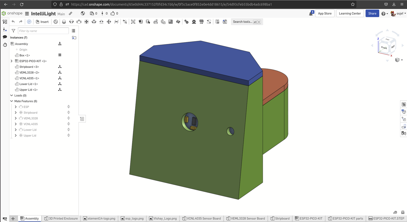
Version 2 of the CAD model for the 3D printed case
In the interests of the community who have been following my project and for those who are trying to get into CAD design and 3D printing, I have used the online editor onshape.com to allow the model to be publicly available and easy to share with the community. The finished model is available here https://cad.onshape.com/documents/65e0d44c337152f0fd34c1bb for anyone interested in looking at it.
Also in order to show my appreciation to the sponsors and organisers of this competition, I have included their company logos on the front face of the 3D printed box. After 7 hours 15 minutes of printing and consuming 57g of matte black PLA material, the updated model was ready for testing out.
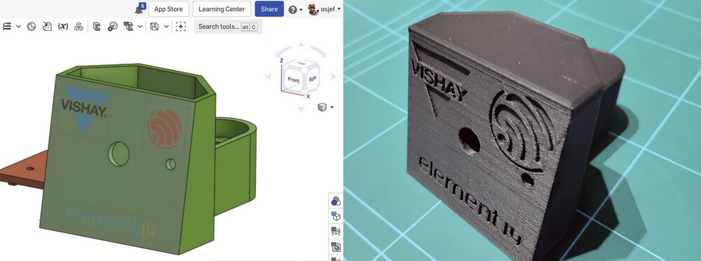
For the second version of the 3D printed box, the Vishay, ESP and E14 logos have been embossed on the front face of the box.
When comparing the two models side-by-side the difference between them is fairly minor. Keeping the redesign simple (rather than completely redesigning the box) was intentional to ensure that the 2nd print would be spot on. If I completely redesigned the CAD model, then the chances are I would need to print out a third model to fix some additional errors in the design. Using this approach, I was able to address all the issue and get a good design with only two prints which helps keep the cost of development and manufacture down. Once again, I’m grateful to my friend who was able to print the model for me whilst my 3D printer is out of action.

Front view of the original model (left) and the new model (right).
Here, the main difference is the addition of the embossed logos, an enlarged cut-out for the proximity sensor and the addition of the hole for the IR LED. These modification were made manually with a drill on the original model to ensure that they would work in the new model.

Rear view of the original model (left) and the new model (right)
The main difference here is the corrected location of the colour sensor hole, removal of the countersunk screw hole (as that is no longer needed since the lids are a good tight fit) and a larger USB cut-out to allow using bulkier USB cables.
Next I removed all the components from the old box and transferred them into the new box. This time everything lined up perfectly and no modifications were required to the box – a very satisfying feeling to be able to assemble the system like a LEGO kit!
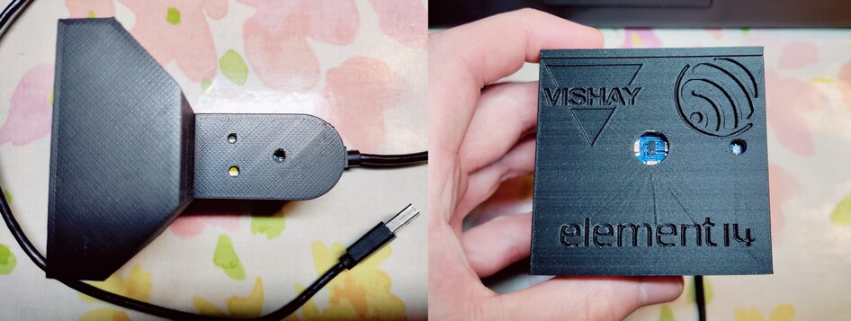
Left: top view showing the LEDs lined up with the holes in the lower lid.
Right: front view showing the proximity sensor and IR LED lined up perfectly.
Calibrating the Sensors
I’ve had the sensors connected and reading using the ESP32 since blog 5, but in order to best utilise the data I needed to “calibrate” them – or at least work out what their usable range is and how that should translate into control for my system. I could not perform this calibration whilst the system was setup on the breadboard as the sensors would be mounted differently in the final box so the values would most likely report differently, so I had to wait till I had printed the box and assembled it all. Once assembled I was able to run the system in a typical environment and print out the sensor readings for the different operating scenarios. This provided me with a minimum and maximum raw sensor reading. For example, the ambient light sensor is being used to control the brightness of the bulb, so I set the system up in the room with the room lights turned out (simulating the darkest scenario) and read the ALS raw sensor reading as “10”. I then turned the room lights on, turned the TV on and opened the curtains to simulated the brightest room lighting. This gave me a raw ALS reading of “70”. Next I had to determine the best minimum and maximum brightness for the smartbulb. After experimenting with different brightness levels, I determined that the minimum brightness should be 20% and the maximum 100%. I then created a basic function to translate these raw readings into brightness data to put into the JSON strings used to control the smartbulb.
/**
* @brief Parameters used to scale raw sensor readings to useful data using a linear scale
*/
struct sensor_scale
{
const uint16_t min_raw; /*!< Raw minimum value */
const uint16_t max_raw; /*!< Raw maximum value */
const uint8_t min_scaled; /*!< Scaled minimum value */
const uint8_t max_scaled; /*!< Scaled maximum value */
};

/**
* @brief Scale raw sensor readings
* @param reading Raw sensor value to scale
* @param scale Sensor scaling data
* @return Scaled value
*/
uint8_t scale_sensor_reading(const uint16_t reading, const struct sensor_scale scale)
{
const uint16_t clipped_value = fmin(fmax(reading, scale.min_raw), scale.max_raw);
const uint16_t range_raw = scale.max_raw - scale.min_raw;
const uint16_t range_scaled = scale.max_scaled - scale.min_scaled;
const float factor = ((clipped_value - scale.min_raw) / (float)range_raw);
return (uint8_t)round((range_scaled * factor) + scale.min_scaled);
}
Then I could set up different scales for each sensor reading like so:
const struct sensor_scale als_scale = {10, 70, 20, 100};
Where 10 is the minimum raw ALS reading, 70 the maximum raw reading and 20% is the minimum brightness and 100% the maximum brightness. Then assuming the ALS response is linear (which is is pretty much) the correct brightness level can be easily calculated.
const uint8_t brightness = scale_sensor_reading(latest_reading, als_scale);
ESP Sleep (Power Saving) Mode
The final finishing touch which I promised to make at the end of my last blog was to investigate the possibility of using the power saving mode of the ESP32 in conjunction with the interrupt output pin (INT) of the VCNL4035 gesture board. The plan is to connect the VCNL4035 INT pin to the ESP32 and configure the gesture board to wake up the ESP32 from its power saving mode based on the distance to the proximity sensor. This way, the ESP32 can be sleeping most of the time (hence saving power) and then when I sit down on my chair the interrupt will trigger the ESP to wake up and then it will do all its clever control of the smartbulb until I get up from the chair at which point the ESP will turn off the light bulb and enter its sleep mode - waiting for its next interrupt.
So I started to look into the sleep mode of the ESP32. This time I needed to refer to the full ESP32 datasheet available here and it turns out there are actually four sleep modes:
- modem sleep
- light sleep
- deep sleep
- hibernation
On one side of the table we have “hibernation” which saves the most power, but the ESP32 can only be woken up using the RTC timer. For example the ESP could be set to periodically wake up every 10 minutes. On the other side, we have “modem sleep” which is the easiest sleep mode to wake up from, but also has the lowest power saving specifications. The the other two sleep modes fall in the middle.
In order to determine which sleep mode to go for, I thought I’d look at the power consumption specifications. On page 32 of the datasheet there is a table showing the typical power consumption for each of the different sleep modes:
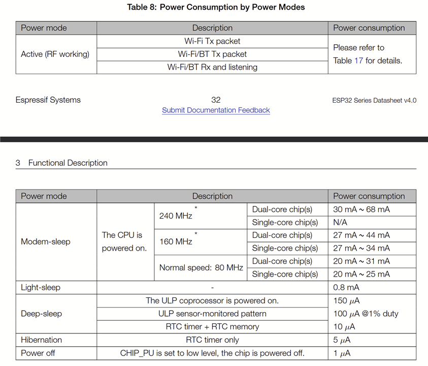
ESP32 power consumption for each sleep mode
So looking at these figures, the best power saving option is “hibernation”. However, as mentioned above, this means that the only way to wake up the ESP32 is to use the timer. This will not work for my particular scenario as I want to wake up the ESP using an interrupt pin. The next level up, “deep sleep” also does a good job of power saving. As can be seen from the following extract of the datasheet, the ESP can be woken up from deep sleep by an “external event”.
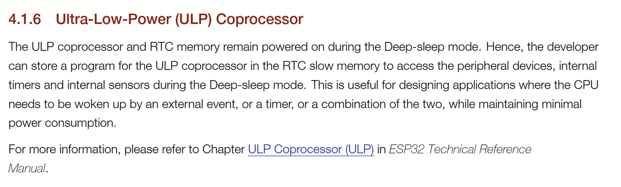
The ESP32 datasheet indicates that the processor can be woken out of a deep sleep using an external event.
The ESP-IDF API reference manual documents this feature very simply here. Basically, the trigger pin needs to be setup and then the ESP can be put into deep sleep mode using the call: “esp_deep_sleep_start()”. The trigger pin must be one of the RTC pins. These are highlighted in cyan in the image below:
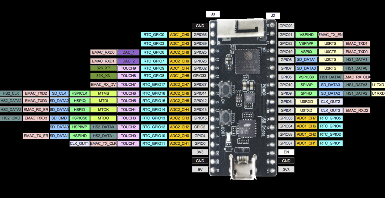
One of the RTC pins can be used for as an external trigger to wake the ESP out of deep sleep mode.
The only RTC GPIO pin that should not be used is GPIO_0/RTC_GPIO_11 as that is connected to the reset button and serves a special purpose, so I selected RTC_GPIO10 and connected it to the INT pin on the VCNL4035 gesture board. Then I made a few modifications to the SW to:
- configure the interrupt pin
- enter deep sleep mode after turning the smartbulb off
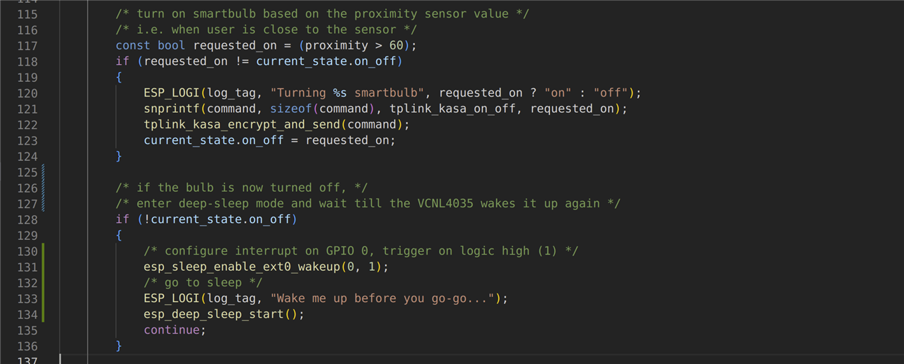
Entering sleep mode after turning off the smartbulb
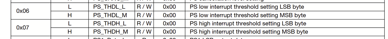
The next stage was to configure the VCNL4035 sensor to trigger when the proximity value exceeds a certain threshold. Looking at the datasheet, the proximity interrupt can be triggered in several ways by configuring the PS_INT field of the PS_CONF2 register.
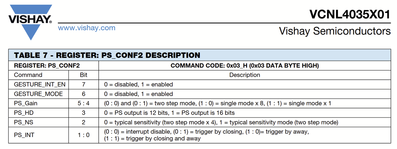
The interrupt can be disabled, triggered when getting closer (i.e. exceeding a high threshold), triggered when moving away (i.e. dropping below a low threshold), or both. The default is disabled. For my scenario, I want the interrupt to be triggered when the proximity reading exceeds 60. Therefore I need to set PS_INT to 1. The threshold is configurable using register 6 and 7 as shown in table 1 of the datasheet.
The full details of those two registers are given a little bit later in the datasheet as shown here:
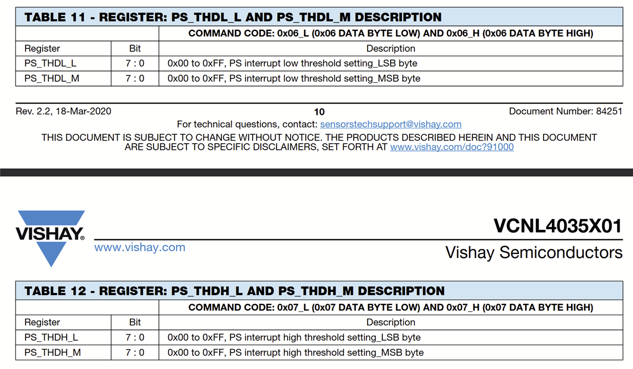
Since I am only interested in the high threshold, I only need to set the PS_THDH register to 60.
In summary, the changes required are:
- Connect the INT pin on the VCNL4035 board to RTC_GPIO11 on the ESP32
- Enable the proximity interrupt (PS_CONF2 . PS_INT = 1)
- Set the high threshold (PS_THDH = 60)
- Enable ext0 interrupt on the ESP32 and configure it to use RTC_GPIO11
- Enter deep-sleep mode after turning the smartbulb off
Additionally there is a interrupt readback register which can be used to readback the expected value of the interrupt. This will be highly useful for debugging, so I also added a fucntion to read this register.
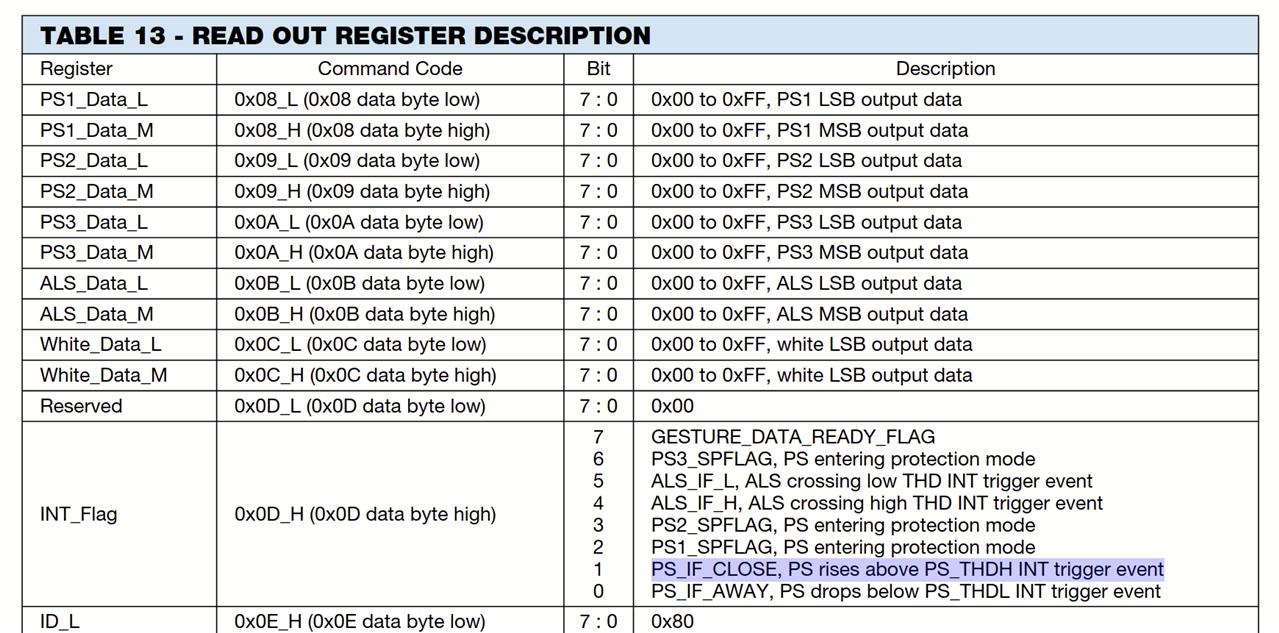
The INT_Flag register can be used to “read back” the expected value of the interrupt.
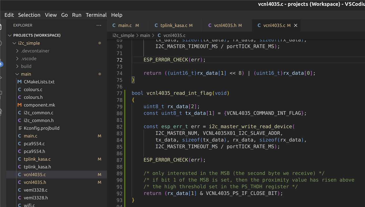
Adding a quick method to read back the INT_Flag register for debugging purposes.
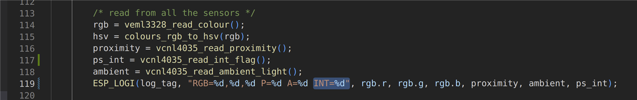
In the main loop, the INT read back is displayed for debugging.
So after making all the required software and hardware modifications, it was ready for final tests.
Increasing the Proximity Detection Distance
One of the issues or concerns I have previously mentioned is that the proximity detection distance I’ve observed during my investigations was quite short – up to a maximum distance of around 20cm. However, whilst reading the application design notes for the VCNL4035 sensor (available here) I spotted a section regarding the use of the sensor for long range detection. This got me interested, so I investigated this further and discovered that the IR LED drive current can be adjusted using a register setting. The higher the current setting, the more powerful the IR LED will shine and hence the transmission distance will be further. This will ultimately increase the proximity detection distance.
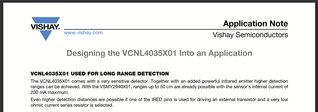
Design notes for the VCNL4035 sensor
According to these design notes, using the maximum IR LED drive current of 200mA will provide a detection distance of up to 50cm. This is much better than what I have been seeing previously as 20cm was borderline far enough to detect me sitting down in a chair (unless the sensor was placed literally on the chair). With a 50cm detection distance, this would allow the sensor to be placed on the table next to the chair (where I originally planned to place the sensor) and still be able to detect when I sit down and stand up. So I looked into the datasheet and found the register settings related to setting the IR LED drive current.
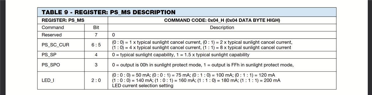
PS_MS register map from the VCNL4035 datasheet
From this extract of the datasheet it is clear to see that if the LED_I field of the PS_MS register is set to 7 (binary 111), this will select the highest LED drive current (200mA) supported using the onboard IR LEDs. So I added another line of code into my sensor configure function and sure enough, the detection distance of the proximity sensor is now much further – around 50cm as expected. Obviously, the raw values returned by the proximity sensor are on a different scale now, so I just had to adjust the threshold for turning the bulb on and off to allow it to work correctly.
Future Enhancements
Dashboard Control
Currently the IP address of the smartbulb is hard-coded in the c code. It would be really nice if there was some sort of nice user interface or dashboard to configure certain settings such as the IP address. Since the ESP32 is already connected to the WiFi, a basic web-server could be written to run on the ESP (there are plenty of demos and tutorials around on how to do this), then you would never have to recompile the code again. You could just log onto the dashboard and set the smartbulb IP address, maybe even the calibration data could be modified if you decide you want the bulb brighter now. A dashboard would be especially handy if you had multiple smartbulbs and could configure them all from one place.
Using the Gesture Feature
One of the nice things about the gesture board is that there are three IR LEDs positioned in such a way as to provide a kind of 3D proximity/gesture mechanism. For example if you are waving your hand in front of the sensors, and the right sensor triggers before the left sensor, this would allow the system to determine that you are moving your hand in a left direction. Because of the position of the IR LEDs, different movements and gestures can be detected like swipe left, swipe right, swipe up, swipe down, move closer, move away etc. For my application, all I have really used the proximity sensor for is to detect proximity in one direction, so there is a lot more that could be done with this sensor. For example, I could use a swipe gesture to temporarily turn the device off to save power, or perhaps another gesture could be used to lock the bulb on if I wanted to go and grab a cup of coffee for a moment.
Bill of Materials (BOM)
This is the final BOM for this project:
| Part | Qty | Notes |
| Vishay VEML3328 | 1 |
Colour sensor to control the smartbulb colour |
| Vishay VCNL4035 | 1 |
Proximity sensor to turn the smartbulb on and off |
| ESP32 | 1 | The microcontroller of the system to read the sensors and control the smartbulb |
| Single-sided copper stripboard | 1 | To assemble the electronic components |
| 2kOhm resistor 5% tolerance | 2 | I2C pull up resistors |
| Multistrand wire | 2m | To connect the sensor boards to the ESP32 |
| 3D printed case | 1 | CAD model available here: https://cad.onshape.com/documents/65e0d44c337152f0fd34c1bb |
| Micro USB cable | 1 | For powering the ESP32 |
| Software to run on the ESP32 | 1 | All source code available here: https://github.com/Mayannaise/intellilight |
Demonstration
The project is now finished and fully working, so I wanted to record a video to show you all. This proved much more difficult in practice - trying to capture the laptop, the sensor box, the lamp and me all in the same frame, so I apologise in advance for the poor quality, however, I hope that it is able to give you a little bit of a view of the system operating:
Conclusion
So today the competition ends. It's been a fun and educational journey for me and hope that it has been interesting for some of my readers too. Many thanks again to Element14 and Vishay for sponsoring this project.
Blog Summary
Part 4 - Unboxing and Evaluation of the Kit
Part 6 - Gesture Board Integration
Part 7 - Smart Bulb Integration
Technical Conclusion
The VEML3328 colour sensor worked fantastically. The first time I used it, I used it with the SensorXplorer USB/I2C bridge and the control GUI that came with the sensor board. This was easy to install and the operation was very intuitive. For my application, the accuracy of the colour value being read was not critical so I never calibrated it with any special equipment, however, to the naked eye the colour values I was seeing seemed about right. The RGB LED worked perfectly and I incorporated that into my system as a form of status LED. Red while booting, blue while connecting to WiFi, and green once running and fully operation. The white LED was really bright and I had no problem controlling that, although I'm not actually using that LED in my final application. I played with the IR sensor a little bit using the evaluation software, but there was no need for it in my application, so I cannot comment on that really.
The VCNL4035 was similarly very easy to setup. The proximity sensor wasn't quite what I was originally hoping it to be, but after modifying a few of the settings, I was to get it to trigger at around 50cm. This is not really a problem with the sensor, just how I was using it in my application, but it all turned out okay in the end.
The only one downside of these two sensor evaluation boards that I have to highlight is the fact that the I2C address is the same for the GPIO controller used to control the LEDs on both boards (as mentioned in one of my earlier blogs). For my application this was not actually a problem as I was not planning on using the arrow LEDs on the gesture board, but it is a bit of a design flaw if you were planning on using all the features from both boards.
The datasheets were easy to use and contained sufficient information to write the code from scratch which I had to do since I was using the ESP32 and no libraries had been created for these devices. If I had used Arduino, then I could have used a premade library, but this was I was able to dig down into the datasheets and get good exposure to them. I also looked at the Vishay application design notes for these boards to determine the correct size holes for my case and these documents were nice and clear with good diagrams.
Personal Conclusion
10 weeks ago I began this project and I set out some aims, objectives and requirements.
The three requirements were to control the on/off state, the brightness and the colour of a smartbulb based on the values of the sensors. This, I am happy to say, has been fully met. Hopefully the video demonstration was able to show each of those three things taking place. I might try and record a better video another time.
My aims were for the product to be low cost, standalone, convenient and eco:
- Other than the cost of the ESP32 which is around £15, there really was not much else to buy.
- The unit is indeed standalone. It requires 5v to power it using a micro USB cable so it can be plugged into a laptop, TV, USB power adapter or even a portable phone battery bank.
- It is very convenient. The 3D printed case makes it nice and sleek and it is quite small so does not take up a lot of room. It boots up in seconds, so you are not waiting for ages for it to turn on.
- Towards the end of the project, I was able to look into the eco-friendly side of it and experiment with the power saving modes of the ESP32 and interrupt feature of the gesture board as documented in this latest blog.
My objectives were to save power, reduce eye tension, and inspire people to discover low cost, useful IoT devices. The power saving options have been detailed comprehensively in this blog as well as a demonstration showing the brightness adjusting. Lastly, I hope I've been able to inspire some people to have a go at making your own IoT system - it doesn't have to be expensive or fancy, there is so much that can be done with just an ESP32 and a little bit of time here and there.
Although I've met all my objectives, there are other improvements and experiments that I would like to do with it at a later date, but for now, my time is up and so I submit my project to the judges. All my source code for the ESP microcontroller as well as the CAD model are available to the community to use as they like (links in the BOM above).
I wish the other competitors the best of luck, and I look forward to taking part in more challenges in the future.
