Welcome
Welcome back to my final blog of this competition. These last few months were fun and very educational, and I hope to compete again in one of these again someday. In this final blog post I will show you how I got the circuit and sensors integrated in my golfcart.
Circuit Board
Here is a picture of the board I used to solder the circuit from last blog on. It fits right on top of the Arduino Uno using some pins on the bottom. This is called a 'hat' for the Arduino, and is common practice used with small circuits to save space. Some manufacturers make premade boards that sit on Arduinos and have function such as reading an SD card or adding a GPS module. The often have headers on top that allows them to be stacked as well. I only need four wire to go to the sensors, the I2C bus (SDA + SCL), 3.3v, and GND. The two large red and black wires go to the buzzer.
The Build
The wire I used for the sensors I got at a yard sale for cheap and has five solid core wires running through it.
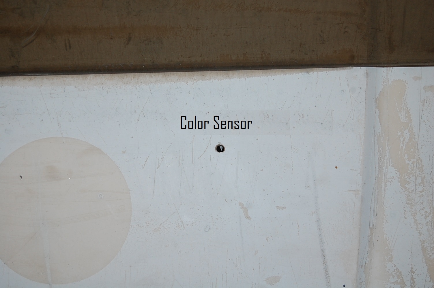
On the golfcart itself I drilled some holes to mount the sensors, the gesture sensor on the back between the brake lights, and the color sensor on the front in the empty space under the dash.


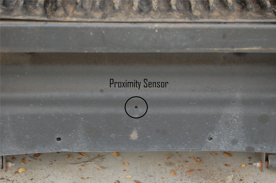
I also put the Arduino & circuit board under the dash behind the ignition key, where I ran the wire for the proximity sensor.
To protect the sensors from the elements I put them each in a waterproof clear plastic box, since when I ran test on the I found they both work fine with a thin piece of clear plastic in front of the sensors.
Here is a simple video showing the sensors on the golfcart. The color sensor isn't installed on the cart yet, but I do have it connected. The proximity sensor is installed and working, which I am happy about. Final Video
Final Thoughts
I am happy I was able to complete my project, as well as learn along the way. There are a few changes I would make in retrospect, among these would be using a music player module with the Arduino instead of the Raspberry pi, as it has a longer start up time then I would prefer, as well as finding a use for the gesture sensing part of the VCNL4035X01 sensor. I also hope I was able to present my journey of discovery well over the last few months and would like to thank the Element14 community for picking me for this competition! Thank you all for reading my blogs, if you missed the last few, I'll put the links to each of my previous blogs below.
Phase 2: Research and Design - Building a Low Voltage Disconnect (LVD) Circuit
Phase 2: Research and Design - Solar Panel Mounting & LVD Circuit Findings
Phase 2: Research and design - Pseudo code for SensorXplorer Board and Programming Raspberry Pi
Phase 2: Research and Design - Prototypes and Programs
Phase 2: Research and Design - Arduino Integration of Sensors


-

dougw
-
Cancel
-
Vote Up
0
Vote Down
-
-
Sign in to reply
-
More
-
Cancel
-

DeltaPi
in reply to dougw
-
Cancel
-
Vote Up
0
Vote Down
-
-
Sign in to reply
-
More
-
Cancel
-

dougw
in reply to DeltaPi
-
Cancel
-
Vote Up
0
Vote Down
-
-
Sign in to reply
-
More
-
Cancel
Comment-

dougw
in reply to DeltaPi
-
Cancel
-
Vote Up
0
Vote Down
-
-
Sign in to reply
-
More
-
Cancel
Children