


 BPM Uno- A Patient Beats Per Minute Heart Rate Monitor
This blog is part of a blog series for the Summer of Sensors -- Under Pressure Design Challenge. This blog is my 6th in a series of blogs that I posted for the challenge .My initial plan for this blog was, to add a new feature to my Arduino prototype sensor stack that I designed and implemented in this blog series. I was only able to get the LSM6DSL Click to operate using the SPI interface, since that is what the click comes configured with. I2C is supported, but you will need to solder some jumpers on the click, to use this interface. I was not aware of this when I started documenting my steps, but I thought to leave my notes here, since it did take me some time and effort to figure this point out. I only experimented with the click and was not able to implement it into my working design.
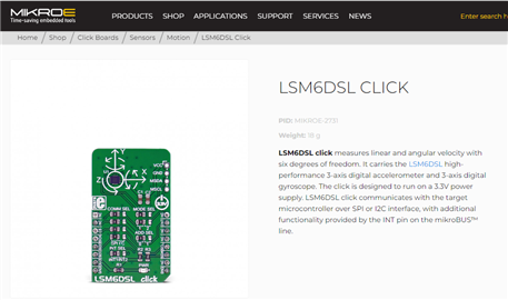
I asked Google what is an LSM6DSL? And here is what came up
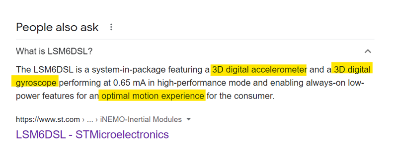
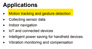 Great, a 3D digital accelerometer/gyroscope from STMicroelectronics. The datasheet suggest a few applications. I might be able to introduce tracking and gesture detection into my BPM monitor. That way I could record the activity of the patent. prior or during a BPM reading. This could be a possibility. But first, I need to find an Arduino library and play around with the LSM6DSL to understand how it works.
The I2C Address
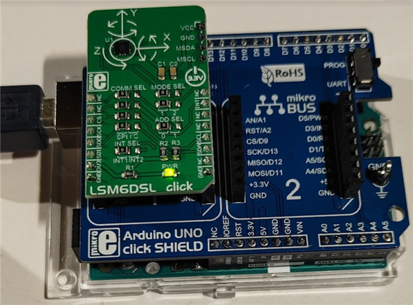
I attached the LSM6DSL CLICK from the supplied kit to the MikroBUS #2 on the MikroE Arduino Uno Click. I plugged the UNO in and my BPM sketch from blog#5 worked fine. I wanted to see if plugging another I2C click would cause a problem. Next I ran my simple i2c_scanner sketch to determine the address of the LSM6DSL. And sure enough, it displays a new address at 0x70 "I2C device found at address 0x70 ". I'm not quit sure why an I2C address is given in the I2C scanner? Since the LSM6DSL jumpers are set to the SPI interface?
Without the LSM6DSL attached |
With the LSM6DSL Attached |
|---|---|
| 7:36:17.551 -> Scanning... 17:36:17.596 -> I2C device found at address 0x03 ! 17:36:17.596 -> I2C device found at address 0x3E ! 17:36:17.643 -> I2C device found at address 0x57 ! 17:36:17.690 -> I2C device found at address 0x62 ! 17:36:17.737 -> done |
17:37:33.823 -> Scanning... 17:37:33.870 -> I2C device found at address 0x03 ! 17:37:33.870 -> I2C device found at address 0x3E ! 17:37:33.918 -> I2C device found at address 0x57 ! 17:37:33.966 -> I2C device found at address 0x62 ! 17:37:34.015 -> I2C device found at address 0x70 ! 17:37:34.061 -> done |
Get an Arduino Library
I found one, on a GitHub repo STEM32duino ,that I will start experimenting with.
I started by cloning the .zip file to my PC and then using the Arduino IDE menu option (Sketch/Include Library/Add ZIP Library..), to include the package. Then I navigated to the example library and started experimenting with the examples. The path is shown below:
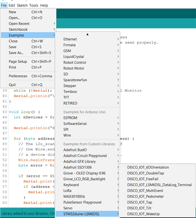
Run an library example
I loaded and tried an example sketch (DISCO_IOT_LSM6DSL_DataLog_Terminal) and received a compile error! 'PB11' was not declared in this scope.
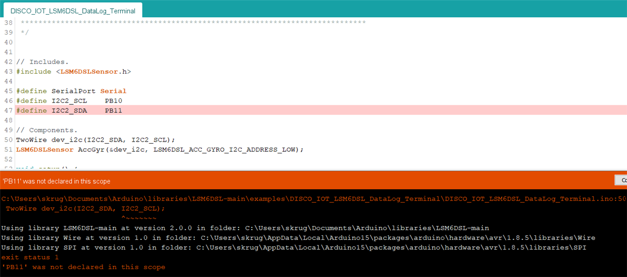
Why is this? I tried other examples and received the same error? why is PB11 not defined? is the library built on the correct wire library?
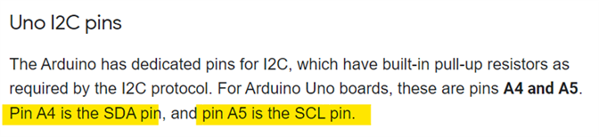
Google says:
I submitted an issue on the Libraries repo and received my answer.
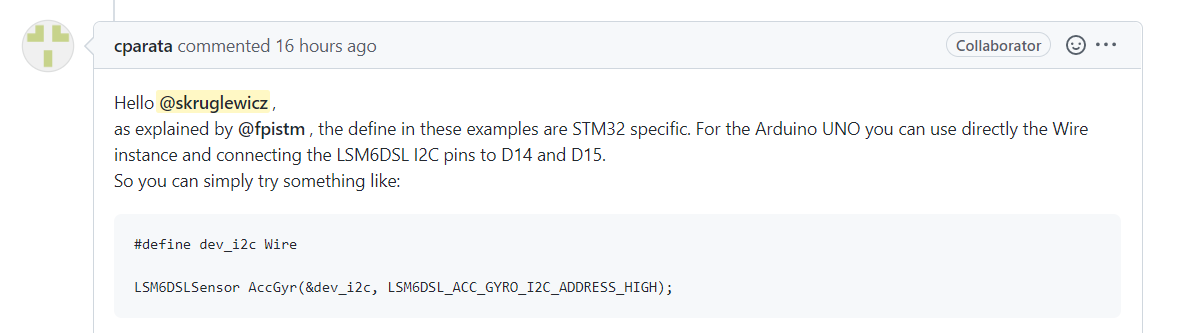
That worked !!! Now I can compile. The code that defined TwoWire was commented and I added the Wire library and defined an instance of the wire object to pass to the LSM6DSLSensor constructor.
// Components.
//TwoWire dev_i2c(I2C2_SDA, I2C2_SCL); //not used for Uno only STM32
#include <Wire.h>
#define dev_i2c Wire
LSM6DSLSensor AccGyr(&dev_i2c, LSM6DSL_ACC_GYRO_I2C_ADDRESS_LOW);
Now when I try to execute the example DISCO_IOT_LSM6DSL_DataLogTerminal.ino on my Uno i get zero values
as follows?
16:35:35.580 -> Acc[mg]: 0 0 0 | Gyr[mdps]: 0 0 0
16:35:36.088 -> Acc[mg]: 0 0 0 | Gyr[mdps]: 0 0 0
16:35:36.602 -> Acc[mg]: 0 0 0 | Gyr[mdps]: 0 0 0
16:35:37.115 -> Acc[mg]: 0 0 0 | Gyr[mdps]: 0 0 0
I'm wondering if the I2c is correct? I have several I2C devices I attached the LSM6DSL CLICK to the MikroBUS #2 on the MikroE Arduino Uno Click.
I have another Issue request on the library repo .
Now I thought to connect the MikroE shield to the UNO, attach the LSM6DSL CLICK , run the i2c scanner, and see what I2C the device is on.
The results was that "No I2C Devices found" ?
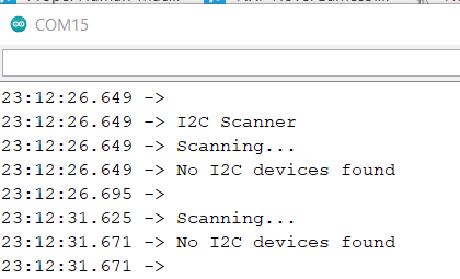
I'm not confident that the LSM6DSL click is working?
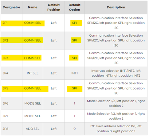
The MikroE LSM6DSL product page describes 2 modes and mode 1 is running the device in slave mode. Which looks like is set?
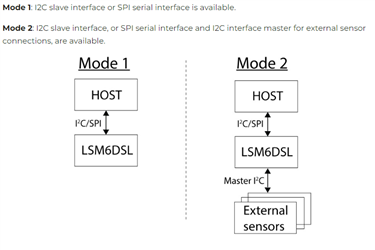
According to the following chart for JP6 and JP7.
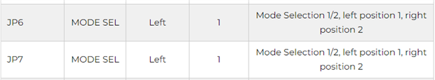
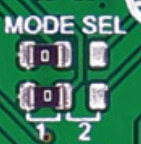
SO WHY is the device not recognized by the I2C scanner.
I'm unable to get the LSM6DSL click to operate. with the I2C interface? If anyone else in the challenge has had some luck with this click leave me a comment.
I received an answer back from my library repo issue question on why I am not able to get the I2C interface to work.
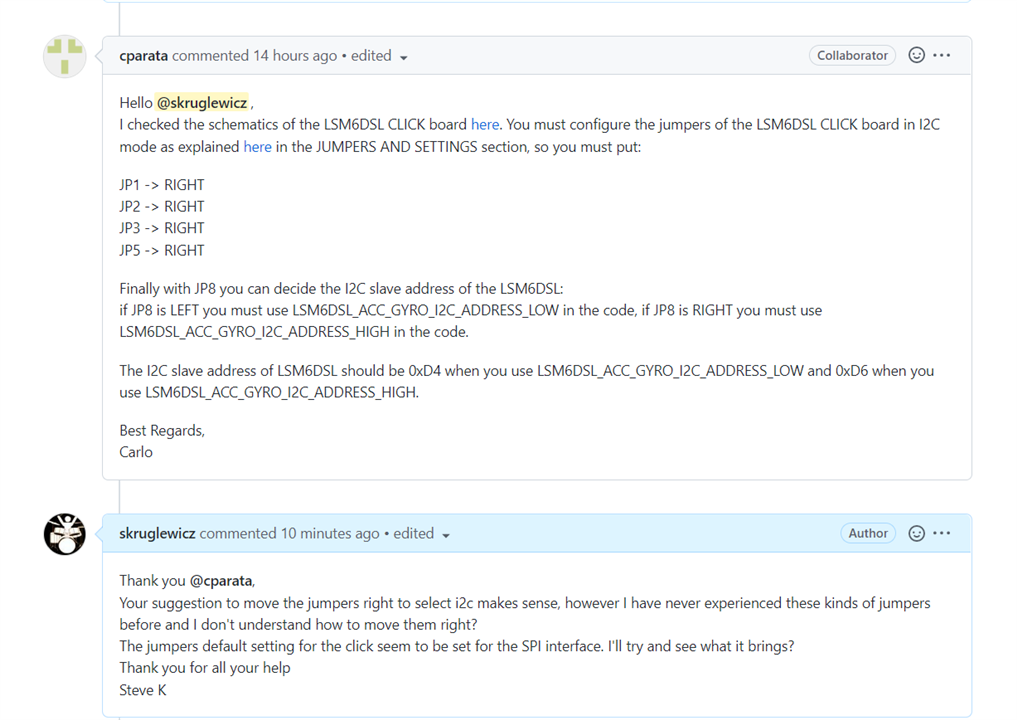
Apparently the Click board comes set to use SPI and you need to change some jumpers on the board to allow the use of the I2C interface.
Not sure how to set these jumpers though , so I'm going to try the SPI interface. So this is the reason the I2C interface is returning zero values.
Using the SPI interface with the library
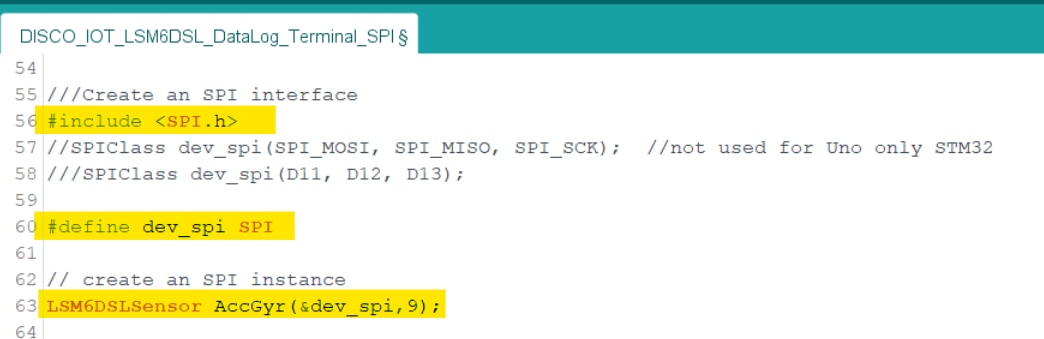
I used the same example (DISCO_IOT_LSM6DSL_DataLog_Terminal) from the Library to test the SPI connection.
/**
 ******************************************************************************
 * @file    DISCO_IOT_LSM6DSL_DataLogTerminal.ino
 * @author  WI6LABS from AST
 * @version V1.0.0
 * @date    7 September 2017
 * @brief   Arduino test application for the STMicrolectronics STM32 DISCO_IOT
 *          MEMS Inertial and Environmental sensor expansion board.
 *          This application makes use of C++ classes obtained from the C
 *          components' drivers.
 ******************************************************************************
 * @attention
 *
 * <h2><center>© COPYRIGHT(c) 2017 STMicroelectronics</center></h2>
 *
 * Redistribution and use in source and binary forms, with or without modification,
 * are permitted provided that the following conditions are met:
 *   1. Redistributions of source code must retain the above copyright notice,
 *      this list of conditions and the following disclaimer.
 *   2. Redistributions in binary form must reproduce the above copyright notice,
 *      this list of conditions and the following disclaimer in the documentation
 *      and/or other materials provided with the distribution.
 *   3. Neither the name of STMicroelectronics nor the names of its contributors
 *      may be used to endorse or promote products derived from this software
 *      without specific prior written permission.
 *
 * THIS SOFTWARE IS PROVIDED BY THE COPYRIGHT HOLDERS AND CONTRIBUTORS "AS IS"
 * AND ANY EXPRESS OR IMPLIED WARRANTIES, INCLUDING, BUT NOT LIMITED TO, THE
 * IMPLIED WARRANTIES OF MERCHANTABILITY AND FITNESS FOR A PARTICULAR PURPOSE ARE
 * DISCLAIMED. IN NO EVENT SHALL THE COPYRIGHT HOLDER OR CONTRIBUTORS BE LIABLE
 * FOR ANY DIRECT, INDIRECT, INCIDENTAL, SPECIAL, EXEMPLARY, OR CONSEQUENTIAL
 * DAMAGES (INCLUDING, BUT NOT LIMITED TO, PROCUREMENT OF SUBSTITUTE GOODS OR
 * SERVICES; LOSS OF USE, DATA, OR PROFITS; OR BUSINESS INTERRUPTION) HOWEVER
 * CAUSED AND ON ANY THEORY OF LIABILITY, WHETHER IN CONTRACT, STRICT LIABILITY,
 * OR TORT (INCLUDING NEGLIGENCE OR OTHERWISE) ARISING IN ANY WAY OUT OF THE USE
 * OF THIS SOFTWARE, EVEN IF ADVISED OF THE POSSIBILITY OF SUCH DAMAGE.
 *
 ******************************************************************************
 */

// Includes.
#include <LSM6DSLSensor.h>

#define SerialPort Serial

// Components.

//// create a TwoWire interface
////TwoWire dev_i2c(I2C2_SDA, I2C2_SCL); //not used for Uno only STM32
//#include <Wire.h>
//#define dev_i2c Wire
//LSM6DSLSensor AccGyr(&dev_i2c, LSM6DSL_ACC_GYRO_I2C_ADDRESS_LOW);
//LSM6DSLSensor AccGyr(&dev_i2c, LSM6DSL_ACC_GYRO_I2C_ADDRESS_HIGH);

///Create an SPI interface
#include <SPI.h>
//SPIClass dev_spi(SPI_MOSI, SPI_MISO, SPI_SCK);  //not used for Uno only STM32
///SPIClass dev_spi(D11, D12, D13);

#define dev_spi SPI

// create an SPI instance
LSM6DSLSensor AccGyr(&dev_spi,9);

void setup() {
  // Led.
  pinMode(LED_BUILTIN, OUTPUT);
  // Initialize serial for output.
  SerialPort.begin(9600);

  // Initialize I2C bus.
  //dev_i2c.begin();

  // Initialize SPI bus.
  dev_spi.begin();

  // Initlialize components.
  AccGyr.begin();
  AccGyr.Enable_X();
  AccGyr.Enable_G();
}

void loop() {
  // Led blinking.
  digitalWrite(LED_BUILTIN, HIGH);
  delay(250);
  digitalWrite(LED_BUILTIN, LOW);
  delay(250);

  // Read accelerometer and gyroscope.
  int32_t accelerometer[3];
  int32_t gyroscope[3];
  AccGyr.Get_X_Axes(accelerometer);
  AccGyr.Get_G_Axes(gyroscope);

  // Output data.
  SerialPort.print("Acc[mg]: ");
  SerialPort.print(accelerometer[0]);
  SerialPort.print(" ");
  SerialPort.print(accelerometer[1]);
  SerialPort.print(" ");
  SerialPort.print(accelerometer[2]);
  SerialPort.print(" | Gyr[mdps]: ");
  SerialPort.print(gyroscope[0]);
  SerialPort.print(" ");
  SerialPort.print(gyroscope[1]);
  SerialPort.print(" ");
  SerialPort.println(gyroscope[2]);
}
The Library Readme describes the API calls used for SPI as follows.
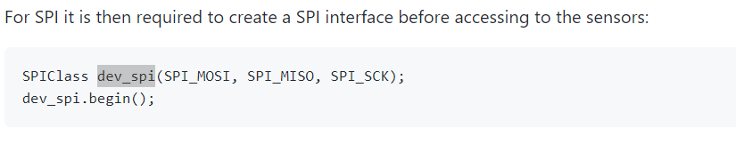
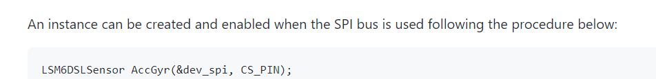
But I assumed, like the I2C example that I needed to include SPI.h, defined dev_spi as SPI. Create an SPI instance. using cs_pin = 9 because that what is on the MikroE shild that the click is pluged into/
I moved the whole prototype around as shown in this video
here is some output:
21:00:50.991 -> Acc[mg]: -31 -5 1063 | Gyr[mdps]: 490 -1610 210
21:00:51.502 -> Acc[mg]: -32 -5 1064 | Gyr[mdps]: 560 -1540 140
21:00:52.014 -> Acc[mg]: -29 -4 1064 | Gyr[mdps]: 560 -1540 210
21:00:52.482 -> Acc[mg]: -30 -3 1064 | Gyr[mdps]: 490 -1540 140
21:00:52.992 -> Acc[mg]: -31 -5 1063 | Gyr[mdps]: 490 -1540 210
21:00:53.504 -> Acc[mg]: -6 -2 1067 | Gyr[mdps]: 490 350 350
21:00:54.018 -> Acc[mg]: -69 20 1060 | Gyr[mdps]: 910 16170 -14280
21:00:54.531 -> Acc[mg]: 115 276 721 | Gyr[mdps]: 130480 -58100 31850
21:00:55.000 -> Acc[mg]: 307 319 925 | Gyr[mdps]: 61600 -22050 3220
21:00:55.512 -> Acc[mg]: 259 -77 1080 | Gyr[mdps]: -44450 -12040 11830
21:00:56.026 -> Acc[mg]: 386 69 964 | Gyr[mdps]: -43960 -33320 2590
21:00:56.497 -> Acc[mg]: 817 -129 639 | Gyr[mdps]: 5880 -79590 6230
21:00:57.007 -> Acc[mg]: 637 -126 844 | Gyr[mdps]: 2660 81970 -3430
21:00:57.522 -> Acc[mg]: 202 -35 1223 | Gyr[mdps]: 1960 -99400 3500
21:00:58.036 -> Acc[mg]: 759 -8 568 | Gyr[mdps]: -29470 -77770 24010
21:00:58.500 -> Acc[mg]: 704 -117 835 | Gyr[mdps]: 24290 109200 -15610
21:00:59.008 -> Acc[mg]: 98 -240 1499 | Gyr[mdps]: -25270 62090 7560
21:00:59.521 -> Acc[mg]: 369 -409 787 | Gyr[mdps]: -24780 -10080 13370
21:01:00.034 -> Acc[mg]: -51 -55 1036 | Gyr[mdps]: -28560 74970 4970
21:01:00.549 -> Acc[mg]: 85 -8 1137 | Gyr[mdps]: -24570 -31640 13580
21:01:01.018 -> Acc[mg]: -55 -18 1107 | Gyr[mdps]: 1400 2730 -14910
21:01:01.532 -> Acc[mg]: -32 -8 1067 | Gyr[mdps]: 350 -1680 210
21:01:02.041 -> Acc[mg]: -35 -4 1066 | Gyr[mdps]: 560 -1610 140
21:01:02.556 -> Acc[mg]: -35 -3 1065 | Gyr[mdps]: 490 -1540 210
21:01:03.019 -> Acc[mg]: -34 -3 1064 | Gyr[mdps]: 560 -1540 210
21:01:03.532 -> Acc[mg]: -35 -5 1063 | Gyr[mdps]: 490 -1470 140
21:01:04.044 -> Acc[mg]: -37 -5 1061 | Gyr[mdps]: 490 -1610 210
21:01:04.558 -> Acc[mg]: -35 -5 1061 | Gyr[mdps]: 490 -1610 140
21:01:05.070 -> Acc[mg]: -35 -5 1063 | Gyr[mdps]: 490 -1540 140
21:01:05.535 -> Acc[mg]: -34 -4 1062 | Gyr[mdps]: 560 -1540 210
Conclusions
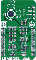
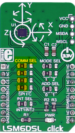
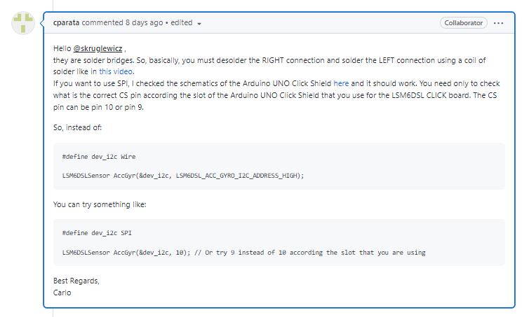
The Jumpers on the LSM6DSL are foreign to me. I'm wondering how to change the COMM SEL jumpers to the RIGHT to use the I2C interface. There is no explanation on the LSM6DSL product page on how to do this? I posed the question to the as a library repo issue question and received my answer! "they are solder bridges. So, basically, you must de-solder the RIGHT connection and solder the LEFT connection using a coil of solder like in this video. I was not in the position to attempt this at the moment, so I decided to investigate the SPI interface
Once I took several days to figure that I2C was not working, I was able to get the SPI interface working with the LSM6DSL click attached to the MikroE shield MikroBUS#2. There must be a bad solder on pin D2 since I only received zero values. Ihe INT pin is on D2 on the MikroBUS#1.
The support for this library is great. I was able to receive my answers to my problems and get it to work with the LSM6DSL!
I will continue to experiment with this prototype and come up with a way to add it to my design. The time is getting short and I'm not sure if I will be able to add this new feature to my design in time for the deadline.
My Bog#5 shows the completed implementation of my design. This blog is more of a proof of concept to get to understand the LSM6DSL capabilities.
The LSM6Click is an interesting Click and I'm real excited to learn more about it.
Top Comments
-

taifur
-
Cancel
-
Vote Up
+1
Vote Down
-
-
Sign in to reply
-
More
-
Cancel
-

skruglewicz
in reply to taifur
-
Cancel
-
Vote Up
0
Vote Down
-
-
Sign in to reply
-
More
-
Cancel
Comment-

skruglewicz
in reply to taifur
-
Cancel
-
Vote Up
0
Vote Down
-
-
Sign in to reply
-
More
-
Cancel
Children