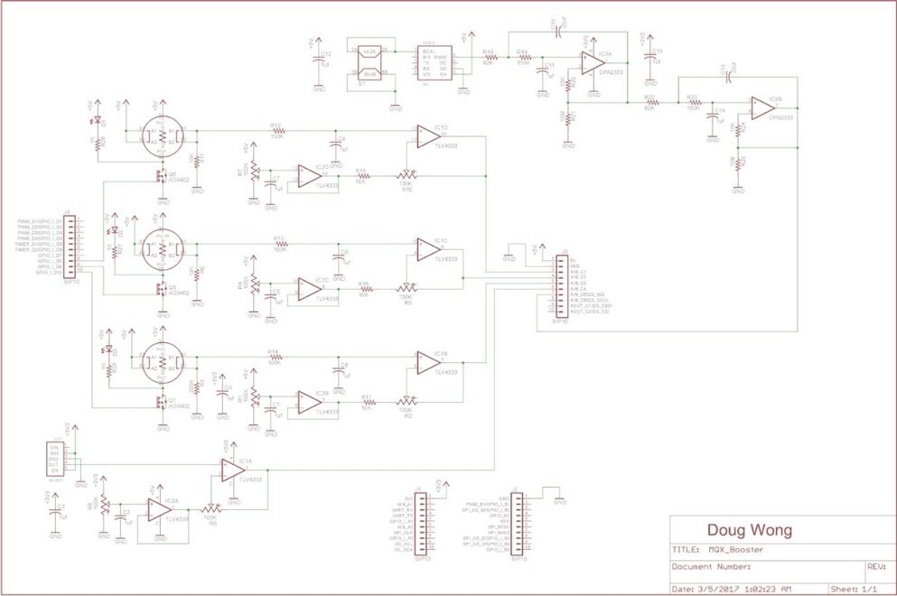
This blog details the circuitry and PCB layout of my custom Booster Pack to monitor 8 hazardous gasses and ultraviolet light. I added some active circuitry to filter the CO2 sensor PWM output since my last blog. This is a 4-pole low-pass Butterworth filter with a cut-off frequency of 10 Hz. (The signal is 1 KHz PWM).
The PCB is laid out to fit on the https://www.element14.com/community/view-product.jspa?fsku=2473128&nsku=41Y9541&COM=noscriptMSP-EXP432P401R MCU as a normal Booster Pack The pins it uses are carefully selected to not interfere with pins used by the 430BOOST-SHARP96430BOOST-SHARP96 LCD or the CC31000ModBoost WiFi nodule
The following table shows the Booster Pack pins used by each of the modules in the kit plus my custom Booster Pack. I have highlighted the modules/pins I will be using. Note there are lots of conflicts if you want to use all of these modules together. They can often be resolved with jumpers on the cards, but the process must be thought through in detail. Even with the modules I have selected, there are a couple of conflicts which I need to resolve. I will permanently enable the LCD, so it doesn't need a control pin and display COM inversion pin will be disconnected and not used. In the end, my project will use 34 of the 40 pins - all of J1 and J2 plus most of J3 and J4.
| Booster | 432P401R | MCU | SHARP LCD | CC3100ModBoost | BoostXL | BoostSense1 | CC2650BLE | DLP7970ABP | MQ_booster | |
| J1-1 | +3.3V | +3.3V | +3.3V | +3.3V | +3.3V | +3.3V | +3.3V | +3.3V | +3.3V | +3.3V |
| J1-2 | Analog In | A15 | P6.0 | LCD Control | LED9 | MRDY | ||||
| J1-3 | UART RX | UART RX | P3.2 | UART RX | TXD | |||||
| J1-4 | UART TX | UART TX | P3.3 | UART TX | RXD | |||||
| J1-5 | GPIO | GPIO 1 | P4.1 | LCD Enable | nHib | INT1 | LEDx | |||
| J1-6 | Analog In | A10 | P4.3 | SPI CS | LED1 | |||||
| J1-7 | SPI CLK | SPI CLK | P1.5 | SPI CLK | SPI CLK | LED2 | SPI CLK | SPI CLK | ||
| J1-8 | GPIO | GPIO 2 | P4.6 | Left Slide 2 | MAG INT | Sens0 | DIO | IRQ | ||
| J1-9 | I2C SCL | I2C SCL | P4.5 | Left Slide 1 | I2C SCL | Sens1 | SPI CS | |||
| J1-10 | I2C SDA | I2C SDA | P4.4 | Left Slide 0 | I2C SDA | Sens2 | EN | |||
| J2-1 | GND | GND | GND | GND | GND | GND | GND | GND | GND | GND |
| J2-2 | GPIO | GPIO | P2.5 | Ext COM Invert | IRQ | SRDY | ||||
| J2-3 | SPI CS W | SPI CS W | P3.0 | SPI CS | SPI CS | Xout | ||||
| J2-4 | GPIO | GPIO | P5.7 | |||||||
| J2-5 | RST | RST | RST | nReset | Reset | |||||
| J2-6 | SPI MOSI | SPI MOSI | P1.6 | SPI SIMO | SPI MOSI | LED4 | MOSI | MOSI | ||
| J2-7 | SPI MISO | SPI MISO | P1.7 | SPI MISO | LED3 | MISO | MISO | |||
| J2-8 | SPI CS D | SPI CS D | P5.0 | Right Slide 2 | INT2 | Sens5 | DIO13 | LED | ||
| J2-9 | SPI CS O | SPI CS O | P5.2 | Right Slide 1 | TMP INT | Sens4 | LED | |||
| J2-10 | GPIO | GPIO | P3.6 | Right Slide 0 | OPT INT | Sens3 | LED | |||
| J3-1 | '+5V | '+5V | '+5V | '+5V | '+5V | '+5V | ||||
| J3-2 | GND | GND | GND | GND | GND | GND | GND | |||
| J3-3 | Analog In 3 | A14 | P6.1 | MQ-7 | ||||||
| J3-4 | Analog In 4 | A13 | P4.0 | MQ-135 | ||||||
| J3-5 | Analog In 5 | A11 | P4.2 | MQ-3 | ||||||
| J3-6 | Analog In 6 | A9 | P4.4 | UV | ||||||
| J3-7 | Analog In 7 | A8 | P4.5 | CO2 | ||||||
| J3-8 | Analog In 8 | A6 | P4.7 | |||||||
| J3-9 | A10 | P5.4 | ||||||||
| J3-10 | A0 | P5.5 | ||||||||
| J4-1 | GPIO | GPIO | P2.7 | |||||||
| J4-2 | GPIO | GPIO | P2.6 | |||||||
| J4-3 | GPIO | GPIO | P2.4 | MQ7D | ||||||
| J4-4 | GPIO | VREF | P5.6 | UART CTS | ||||||
| J4-5 | GPIO | GPIO | P6.6 | UART RTS | ||||||
| J4-6 | GPIO | GPIO | P6.7 | nReset | ||||||
| J4-7 | GPIO | GPIO | P2.3 | NWP Log TX | ||||||
| J4-8 | GPIO | GPIO | P5.1 | WLAN Log TX | ||||||
| J4-9 | GPIO | GPIO | P3.5 | MQ135D | ||||||
| J4-10 | GPIO | GPIO | P3.7 | MQ3D |
Hopefully this table will save some of the other contestants some work, although they will still need to check everything.
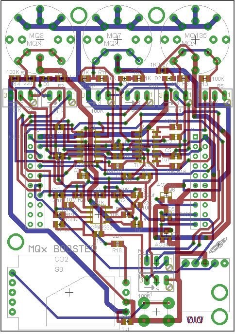
The PCB layout is shown below. It is intended to sit above the MCU, but below the LCD. The WiFi module will go below the MCU. The sensors will surround the LCD without increasing the width of the whole stack. This is because I have to mount three other instrument clusters on my arm beside this sensor stack.
Now that I am finally getting this card on order, I can start working on the radiation aspects of this project. I have already learned a lot with the research I have done on environmental gasses and environmental radiation work looks to be at least as involved.
All links to blogs related to this project can be found in the first blog here:
Safe and Sound - Invisible Hazardous Environmental Factors Monitoring System - blog 1


Top Comments
-

DAB
-
Cancel
-
Vote Up
+3
Vote Down
-
-
Sign in to reply
-
More
-
Cancel
-

dougw
in reply to DAB
-
Cancel
-
Vote Up
0
Vote Down
-
-
Sign in to reply
-
More
-
Cancel
Comment-

dougw
in reply to DAB
-
Cancel
-
Vote Up
0
Vote Down
-
-
Sign in to reply
-
More
-
Cancel
Children