This is in continuation from my previous post at Safe & Sound - The Companion IoT Jacket #10: MSP432, BLE and 3D Printing module one
In this post, I add an energy harvesting LCD display to my wearable design and add some basic test results and an enclosure.
The Second Module: An Energy Harvesting Display
In order for the wearable to have a user interface, the Sharp96 Booster Pack was selected. The 96px x 96px real-estate is enough to present relevant information in a compact and efficient manner. Since mounting the entire MSP432 launchpad together seemed to defeat ergonomics, I elected to use my DIY MSP430 econopad. To add to the uniqueness of the design, the BS25570EVM was employed with a solar panel and a 0.1F super capacitor to power the display part of the design. The diagram below shows the second module as it plays out in the final design.
Let us take a look at each of the above modules one by one.
a. The Econopad and MSP430 TLV code
I have explained the MSP430 Econopad in TI Econo Launchpad for DIY People and Safe & Sound - Safety Jacket for the Tolling Industry #4: Unboxing and a relaunchpad
The Sharp 96 Boosterpack mounts atop the DIY PCB which has an MSP430G2553 micro controller. The firmware for the device uses existing Sharp96 drivers combined with a TLV like protocol as explained in the previous post at Safe & Sound - Safety Jacket for the Tolling Industry #6: Writing your own protocol - part 2
The controller only receives information via UART at 9600bps which have 4 characters transmitted simultaneously. Delays in between characters is treated as a timeout and results in a reset of the state machine. The first character indicates the data type and the next three characters are the data. The following characters are used:
T- Temperature
P-Pressure
H-Humidity
A-Alerts
M-Messages
The alerts are predefined messages stored in the controller and invoked to display messages on the screen. The Battery percentage is displayed in the form of a progress bar. The serial communication happens via interrupts and the main routine waits for a complete and valid frame to arrive. The entire screen is refreshed even if a single value is changed and hence it is the task of the MSP432 to send data only when required.
b. Communications
The uart on the MSP432 is used by the CC2650 driver hence the backchannel uart is brought into play. Every task sends data to the display to update the data. e.g. The temperature task send temperature data overtime there is a relevant change. A dedicated task is used to get messages over BLE and send commands for the messages and alerts.
The MSP432 does not receive any data from the display as this would cause unnecessary delays in the routines. Communications are reconfigured to 9600bps instead of the default 115200bps.
c. Energy Harvesting Investigation
I investigated the use of the BQ25570EVM in a previous blog post at Safe & Sound - Safety Jacket for the Tolling Industry #8: Energy Harvesting
Further analysis confirmed that the MSP430 and the Sharp96 Booster pack only draw 330uAmps of current at 1.8V which means that the system can operate on the harvested energy. The internal buck converter comes preconfigured to provide 1.8V and the jumpers were set so that the internal high efficiency buck converter would keep operating until the supercap was discharged to 1.8V. This adds a longer lifetime to the display which is only usable in well lit areas.
The graph above shows the discharge of the superCap over time with a 25 Second per division.
When the solar panel is exposed to ambient light inside a room, the charge rate is greater than or equal to the discharge rate.
This brings us to the conclusion that the small sized solar panel is sufficinent considering the high efficiency BQ25570.
d. The Enclosure
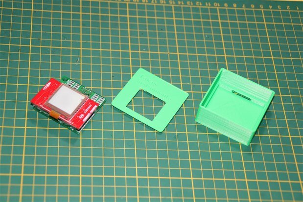
Making this part wearable was a bit of a challenge since hanging a solar panel on a jacket would be non-ergonomic. A thin box was created with exact dimensions to fit the EVM as well as the SuperCap. The result is shown below. The box has space to attach straps and be mounted onthe jacket.
Conclusion
This modules is a reusable segment and is designed separately. This modular approach allows for reusability of the design and can be adopted to other projects. The code will be available on GitHub for download along with the rest of the project.
I am happy that I was able to incorporate the EVM directly into my design and in the next part I take a look at the power supply for the main module.


Top Comments