Title: Wearable Tracking Device for Miners
By: sunnyiut
| Previous Blogs | |
|---|---|
| 01: Introduction | 02: The Kit |
| 03: Review_MSP432P401R | 04: Review_430BOOST-SHARP96 |
| 05: Review_BOOSTXL-SENSORS |
Design Challenge: Safe and Sound Wearables
Blog number: 06
Intro:
It's my 4th blog on KIT review and this time I'll check out the DLP-7970ABPDLP-7970ABP NFC/RFID r eader/writer module. This booster pack has TRF7970A NFC transceiver and communicates with the MCU using SPI protocol.
I'll be using MSP-EXP432P401RMSP-EXP432P401R launchpad to read and write the RFID tag included with the boosterpack and a PC GUI to display the contents of the tag 
Features:
- Integrated 13.56 MHz NFC/ HF RFID IC
- Supports ISO 15693, 18000-3, 14443A/B, and FeliCa
- Supports three different modes
- RFID/NFC Reader
- NFC Peer
- In Card Emulation mode
- Supports NFC Type 2, 3, 4A, 4B, and 5 Tag Platforms
- Package includes 1 Type 2 NFC Tag
Review Description:
example codes:
Read and write Data from the TAG using SPI comm with TRF7970A
Example codes has been taken from TI product page reference design.
1.Near Field Communication (NFC) Reader/Writer Reference Design
IDE: Code Composer Studio v7.1.0
Resource: Resource Explorer [dev.ti.com/tirex]
Launchpad MSP-EXP432P401RMSP-EXP432P401R
GUI: TIDM-NFC-RW Software (Rev. A)
Demonstrates -
- detecting the TAG and read data from the memory blocks
- communicating with PC GUI through UART to display data and TAG information
- write new data to the TAG using the text editor in the GUI software
Board Connection:
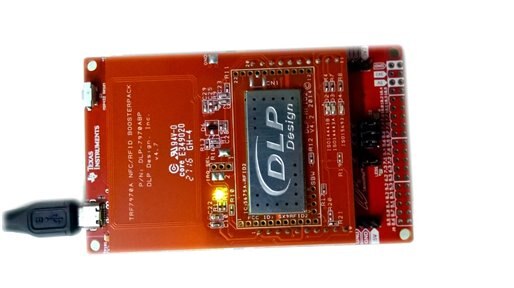
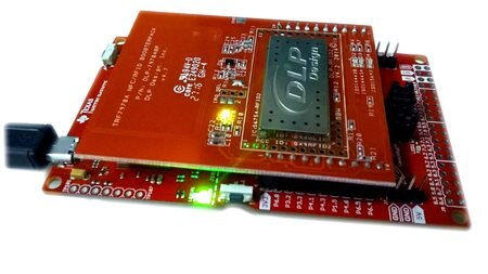
After mounting the DLP NFC BoosterPack, The power LED turns on.
However, PORT1.0 LED is still off which indicates that the UART communication with PC GUI software is not established.
GUI:
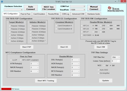
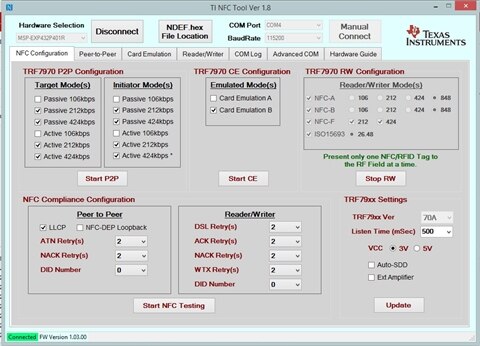
The GUI needs to configure the serial COM port to establish connection with the launchpad.
in my case it was -
COM port : 4
BAUDrates : 115200
we can select "auto connect" where, the GUI software automatically tries out all the COM ports and connects to the Launchpad.
Launchpad not connected to the GUI Connection established on COM4 @ 115200
When the GUI software and the Launchpad establish the connection between them, the red LED [@P1.0] turns on. If the RFID tag is placed near the onboard antenna, the DLP 7970ABP detects the TAG and turns on the Blue LED [@P2.2].
This blue LED indicates that the R/W function is taking place and the GUI displays the data inside the TAG on 'Reader/Writer window.
Operating distance [max] : ~35mm
At the left side of the window, it presents the TAG information:
TAG type: T5T
Technology: NFC-V
ID: 0xE00700001ED1AD82
The right side of the window presents the data stored inside the Memory Blocks of the Tag.
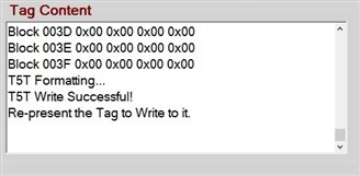
This GUI gives the facility of Formatting the blocks and writing new data into the Tag.
Formatting the TAG erases the data inside the blocks and prepare the tag for new data to be written.
Writing new data into the tag can be done easily by editing the Text inside the text editor and clicking the WRITE button.
There is a URL editor by which an URL can be written into the tag:
Project Update:
In my project proposal for 'SAFE & Sound' design challenge, I'll be using the MSP432P401r for designing a wearable device which will have the sensors connected. But to implement the RFID reader i'll need another MCU and I don't have another MSP432 with me right now. Also this T5T tags are not available in my locality, So I cannot test the system for multiple entries.
Considering all these staff I'll go for some other solution which I have in my hand right now, for designing my system.






Top Comments
-

DAB
-
Cancel
-
Vote Up
+1
Vote Down
-
-
Sign in to reply
-
More
-
Cancel
Comment-

DAB
-
Cancel
-
Vote Up
+1
Vote Down
-
-
Sign in to reply
-
More
-
Cancel
Children