


Success Is Worth Sharing
Today was my test of my system and it was successful. Here is a video showing it working.
(Video is not the best as it shows extra command that are in the future.)
Here are some pictures of what I tested
| {gallery} My Gallery Title |
|---|
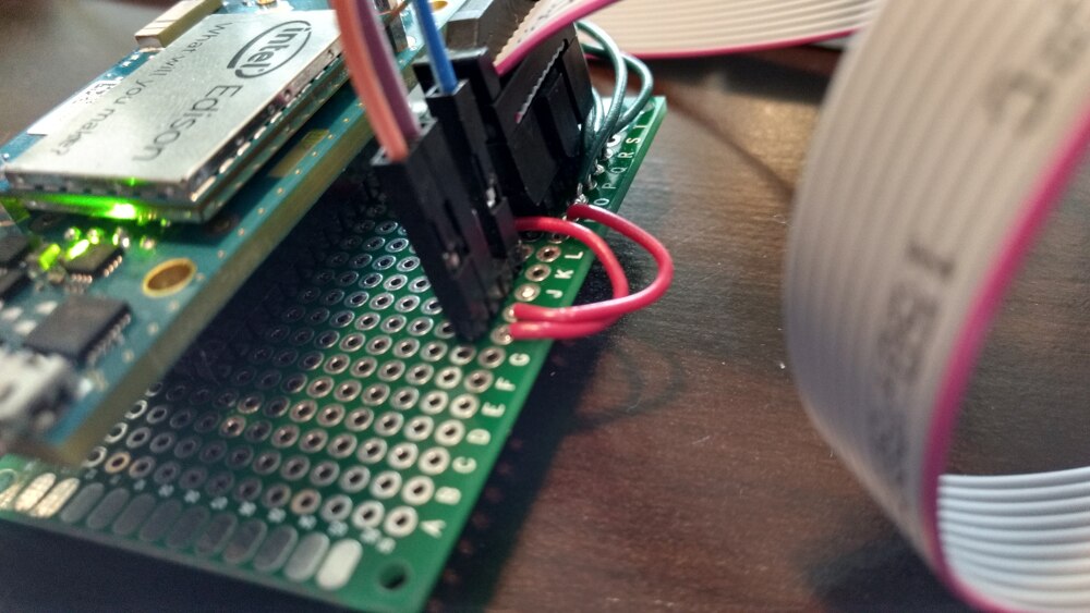
Edison interface to protoboard |
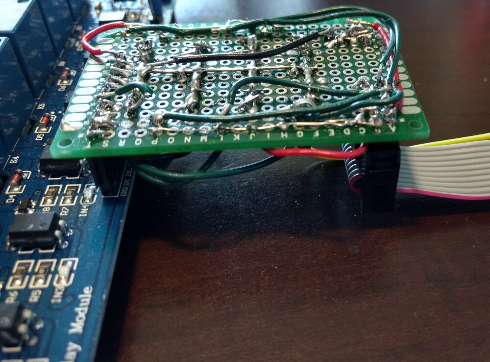
Ribbon header goes to Relay board |
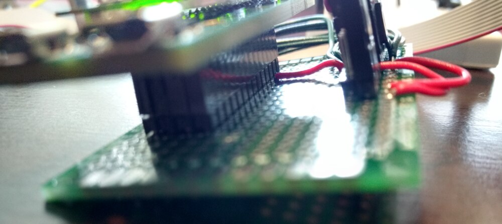
Top view!! |
Relay board hooked up and running. |

Here is the Node-Red flow that I used to test with. Note the first flow, it does monitor the GPIO for changes and with the RBE (Report By Exception) will tell us when the value changes. I will use this to send out messages on change of outlet statuses and to store that information in the Mongo database.

Edison Interface
I used my protoboard to create 4 rows of male header pins to interface with the 4 rows of female header pins I had put on the Edison Mini board earlier. Then I wired up pin J17-4 to 12V and pin J19-3 to ground. I wired up GPIO lines from J20-4 through J20-11 to the header going to the relay board. The 12V is also taken to this header so that it can be converted to 5V and returned for future use.
This week gpolder posted the following image on Workshopshed's post and it gets my vote for the most useful. Some pins cannot be used, so I tested them before hand to make sure that J20-4 ... J20-11 could all be used for GPIO. For example GP134 on pin J20-3 does not work in Node-Red with the Johnny-Five controls.

| GPIO | Output Label |
|---|---|
| GP78 | Outlet 1 |
| GP41 | Outlet 2 |
| GP84 | Outlet 3 |
| GP42 | Outlet 4 |
| GP15 | Outlet 5 |
| GP49 | Outlet 6 |
| GP47 | Outlet 7 |
| GP45 | Outlet 8 |
About The Video
Video was a screen capture with a webcam feed and putty shell. Here is my webcam setup. Yes, it is an old Android phone running as a web cam.

Finishing List
- Shift converters with LCD
- Mount LCD
- Mount Relay board and Edison board
- Wire relay board to outlets
- Web interface
- MQTT emergency response
- LED indicators
- Something cool in the old Serial port hole


