


In the previous post, I looked at Hooking up the Furby to the Edison. Now to put that together with some software so we can control what the Furby does.
Motor
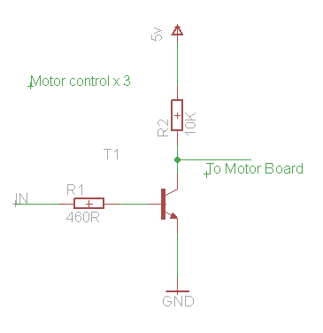
Driving the motor from the H-Bridge board is pretty much the same as per [Upcycle It] Interactive Race Car Driver - Powering Motors although there are the extra transistor level shifters to factor in. This means all of the signals are inverted.
MCU
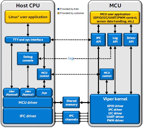
As I discovered that the rate of pulses from the optical sensor is quite high, I decided that the of the Edison would be ideal to monitor the inputs. Then a Node program can be used to get the current value of the counter from the MCU. So that the MCU knows which direction that the Furby's cam wheel is rotating a simple message can be sent over the serial communications channel.
Installing the MCU SDK
Installation of the SDK is straightforward, it's an Eclipse-based application so to get that to work on Windows there are quite a few extra components to install such as JRE and Cygwin.
I did have a few issues creating projects and this seemed partly due to my Workspace folder and partly because of my installation.
Ensure you:
- Keep paths short
- Keep paths without spaces in them
- Install all of the components
- Set the Environment variable
Target IP
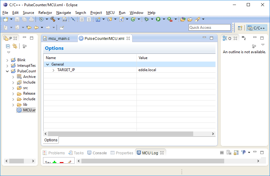
Unlike a lot of embedded SDKs the MCU SDK uploads the code over the network. So before you can upload your project you need to set the TARGET_IP. So I set that to the name of the board and it worked just fine.
For .local addresses to work on Windows, you might need to install a service such as Bonjour
https://learn.adafruit.com/bonjour-zeroconf-networking-for-windows-and-linux/overview
Sample Scripts
There are some tools that can help to configure the ports, it's worth downloading these as unlike things like MRAA, the MCU code "gpio_setup" does not actually configure the hardware to be an input or output.
Sample scripts for the MCU SDK
I installed the init_DIG script as follows:
mkdir tools
cd tools
wget http://downloadmirror.intel.com/24910/eng/init_DIG.sh
chmod +x init_DIG.sh
cd ..
Then configured a couple of the pins with:
./tools/init_DIG.sh -o 7 -d input
./tools/init_DIG.sh -o 8 -d input
This article Using an mcu on the intel edison board with the ultrasonic range sensor confirms that you need to do this each time the Edison boots. I'm also wondering if I can use MRAA to configure the ports in the control code for the Furby.
Testing
For initial testing, I used the grove shield, a switch for counting and capacitive sensor for reset.
The MCU application detects the signals with the aid of two interrupt handlers.
gpio_register_interrupt
Register an interrupt handler for one GPIO port.
int gpio_register_interrupt(int gpio, int mode, irq_handler_t isr);
...where:
- gpio: GPIO port number
- mode: 0 = falling edge interrupt, 1 = rising edge interrupt
- isr: interrupt handler function
- Return value: 0 if successful
The status is reported via the debug port and the current count can be received via the host to mcu serial port /dev/ttymcu0. I limited the counts to 50 for this initial testing to check it wrapped around correctly.
MCU Test code
#include "mcu_api.h"
#include "mcu_errno.h"
volatile int counter;
volatile int direction;
int maxPulses;
 int IRQpulse(int req)
 {
   counter += direction;
   if (counter < 0) {
    counter = maxPulses;
   }
   if (counter > maxPulses) {
    counter = 0;
   }
   debug_print(DBG_INFO, "Counter: %d\n",counter);
   return IRQ_HANDLED;
 }
 int IRQreset(int req)
 {
   counter = 0;
   debug_print(DBG_INFO, "Reset.\n");
   return IRQ_HANDLED;
 }
 void mcu_main()
 {
 char buf[64];
 char response[20];
    int retCode;
    int len;
    debug_print(DBG_INFO, "mcu app starting...\n");
    direction = 1;
    maxPulses = 50;    //Max pulses per revolution (need to find this experimentally)
    gpio_setup(48, 0);  /* set GPIO 48 DIG7 as input*/
    gpio_register_interrupt(48, 1, IRQpulse);
    gpio_setup(49, 0);  /* set GPIO 49 DIG8 as input*/
    gpio_register_interrupt(49, 1, IRQreset);
    while (1)
    {
     //Wait for command from host
     do {
      retCode = host_receive((unsigned char *)buf, 64);
         mcu_sleep(10);
     } while (retCode <= 0);
     switch(buf[0]) {
        case 'C'  :
         debug_print(DBG_INFO, "Counter: %d\n", counter);
         debug_print(DBG_INFO, "Direction: %d\n", direction);
         len = mcu_snprintf(response, 20, "C%d\n", counter);
         host_send((unsigned char*)response, len);
            break;
        case 'U'  :
        debug_print(DBG_INFO, "Up\n");
        direction = 1;
           break;
        case 'D'  :
        debug_print(DBG_INFO, "Down\n");
        direction = -1;
           break;
     }
    }
 }
I could not get Eclipse to display the debug log but from a console I could display it with:
cat /dev/ttymcu1 &
To interact with the MCU I used the 3 letters, C to display counter, D to count down and U to count up.
echo C > /dev/ttymcu0
echo D > /dev/ttymcu0
echo U > /dev/ttymcu0
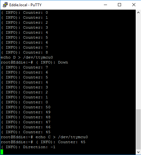
The reset and pulse counters proved to work correctly. There are reports of the MCU not being able to cope with very high pulse rates. If this is the case I'll drop the debug statements and change the speed of the motor until it works reliably.
Monitoring the position
Once I was happy the MCU was working as expected I hooked the inputs upto the Furby. So that I could move both forward and backwards I needed to know the maximum number of pulses. To find this, I set the max in code to a large number and planned span the motor by hand.
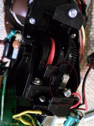
Initially when I set this up the reset line was going wild. I used a resistor to pull that high and confirmed it worked by manually closing the contacts.
I manually span the slotted disk and after a short delay I got a reading of 209 pulses. Note to self, that needs to go to 1.8v when it's wired up to the mini-breakout.
I repeated this experiment with the motor driven from a battery and there was a debounce problem where I was getting multiple resets. Given that it was a mechanical spring contact this is not surprising. I added a simple delay into the reset interrupt handler and that improved the problem but did not completely eliminate the problem with a "bounce" appearing 7 or so pulses later. I'll likely use a mechanism where the reset initialtes a countdown and can't be retriggered until 10 or more pulses have been detected.
These experiments did provide repeated results of 208 pulses per revolution. I added that into the code and also added a call via the host API to return this max value. This experiment also demonstrated that the MCU was happily counting pulses and not obviously skipping.
Latest MCU code
#include "mcu_api.h"
#include "mcu_errno.h"
volatile int counter;
volatile int direction;
int maxPulses;
 int IRQpulse(int req)
 {
   counter += direction;
   if (counter < 0) {
    counter = maxPulses;
   }
   if (counter > maxPulses) {
    counter = 0;
   }
   debug_print(DBG_INFO, "Counter: %d\n",counter);
   return IRQ_HANDLED;
 }
 int IRQreset(int req)
 {
   counter = 0;
   mcu_sleep(20);  //Debounce
   debug_print(DBG_INFO, "Reset.\n");
   return IRQ_HANDLED;
 }
 void mcu_main()
 {
 char buf[64];
 char response[20];
    int retCode;
    int len;
    debug_print(DBG_INFO, "mcu app starting...\n");
    direction = 1;
    maxPulses = 208;    //Max pulses per revolution, was determined experimentally
    gpio_setup(48, 0);  /* set GPIO 48 DIG7 as input*/
    gpio_register_interrupt(48, 1, IRQpulse);
    gpio_setup(49, 0);  /* set GPIO 49 DIG8 as input*/
    gpio_register_interrupt(49, 1, IRQreset);
    while (1)
    {
     //Wait for command from host
     do {
      retCode = host_receive((unsigned char *)buf, 64);
         mcu_sleep(10);
     } while (retCode <= 0);
     switch(buf[0]) {
        case 'C'  :
         debug_print(DBG_INFO, "Counter: %d\n", counter);
         debug_print(DBG_INFO, "Direction: %d\n", direction);
         len = mcu_snprintf(response, 20, "C%d\n", counter);
         host_send((unsigned char*)response, len);
            break;
        case 'M'  :
         debug_print(DBG_INFO, "Max: %d\n", maxPulses);
         len = mcu_snprintf(response, 20, "M%d\n", maxPulses);
         host_send((unsigned char*)response, len);
            break;
        case 'U'  :
        debug_print(DBG_INFO, "Up\n");
        direction = 1;
           break;
        case 'D'  :
        debug_print(DBG_INFO, "Down\n");
        direction = -1;
           break;
     }
    }
 }
What next?
Test the H-Bridge with the mini-breakout and level shifters
Test the Sensors with the mini-breakout and level shifters
Write some high-level control code that communicates with the MCU and uses the counts from the Northwestern team to drive specific motions e.g. talking, ears waggling.
Reference
Registering_an_interrupt_handler_to_a_GPIO_port
Using an mcu on the intel edison board with the ultrasonic range sensor
Sample scripts for the MCU SDK
Previous Posts
Upcycle It Blogs tagged with upcycled_interactiveracecardriver
Top Comments