element14 Community
element14 Community
    Register Log In
  • Site
  • Search
  • Log In Register
  • Community Hub
    Community Hub
    • What's New on element14
    • Feedback and Support
    • Benefits of Membership
    • Personal Blogs
    • Members Area
    • Achievement Levels
  • Learn
    Learn
    • Ask an Expert
    • eBooks
    • element14 presents
    • Learning Center
    • Tech Spotlight
    • STEM Academy
    • Webinars, Training and Events
    • Learning Groups
  • Technologies
    Technologies
    • 3D Printing
    • FPGA
    • Industrial Automation
    • Internet of Things
    • Power & Energy
    • Sensors
    • Technology Groups
  • Challenges & Projects
    Challenges & Projects
    • Design Challenges
    • element14 presents Projects
    • Project14
    • Arduino Projects
    • Raspberry Pi Projects
    • Project Groups
  • Products
    Products
    • Arduino
    • Avnet & Tria Boards Community
    • Dev Tools
    • Manufacturers
    • Multicomp Pro
    • Product Groups
    • Raspberry Pi
    • RoadTests & Reviews
  • About Us
  • Store
    Store
    • Visit Your Store
    • Choose another store...
      • Europe
      •  Austria (German)
      •  Belgium (Dutch, French)
      •  Bulgaria (Bulgarian)
      •  Czech Republic (Czech)
      •  Denmark (Danish)
      •  Estonia (Estonian)
      •  Finland (Finnish)
      •  France (French)
      •  Germany (German)
      •  Hungary (Hungarian)
      •  Ireland
      •  Israel
      •  Italy (Italian)
      •  Latvia (Latvian)
      •  
      •  Lithuania (Lithuanian)
      •  Netherlands (Dutch)
      •  Norway (Norwegian)
      •  Poland (Polish)
      •  Portugal (Portuguese)
      •  Romania (Romanian)
      •  Russia (Russian)
      •  Slovakia (Slovak)
      •  Slovenia (Slovenian)
      •  Spain (Spanish)
      •  Sweden (Swedish)
      •  Switzerland(German, French)
      •  Turkey (Turkish)
      •  United Kingdom
      • Asia Pacific
      •  Australia
      •  China
      •  Hong Kong
      •  India
      • Japan
      •  Korea (Korean)
      •  Malaysia
      •  New Zealand
      •  Philippines
      •  Singapore
      •  Taiwan
      •  Thailand (Thai)
      • Vietnam
      • Americas
      •  Brazil (Portuguese)
      •  Canada
      •  Mexico (Spanish)
      •  United States
      Can't find the country/region you're looking for? Visit our export site or find a local distributor.
  • Translate
  • Profile
  • Settings
Upcycle It
  • Challenges & Projects
  • Design Challenges
  • Upcycle It
  • More
  • Cancel
Upcycle It
Blog [Upcycle It] Interactive Race Car Driver - Hooking up the Furby
  • Blog
  • Forum
  • Documents
  • Polls
  • Files
  • Events
  • Mentions
  • Sub-Groups
  • Tags
  • More
  • Cancel
  • New
  • Share
  • More
  • Cancel
Group Actions
  • Group RSS
  • More
  • Cancel
Engagement
  • Author Author: Workshopshed
  • Date Created: 21 May 2017 8:20 PM Date Created
  • Views 1752 views
  • Likes 6 likes
  • Comments 8 comments
  • upcycled_interactiveracecardriver
Related
Recommended

[Upcycle It] Interactive Race Car Driver - Hooking up the Furby

Workshopshed
Workshopshed
21 May 2017

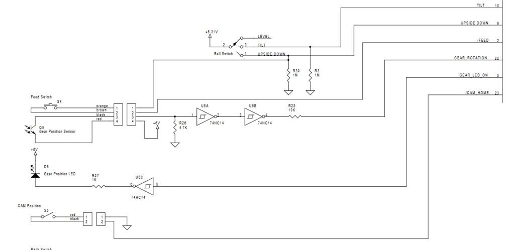
As mentioned in the Furby Hacking post the Furby is powered with a motor and cam system with different actions at different points in the rotation. The position of the cams is determined by a simple spring switch that is closed once per revolution. Then the relative position is determined using an optical sensor consisting of an LED, phototransistor and some buffers. So to control all this from the Edison I need to provide power to the 74HC14 chip, turn on the LED, monitor the gear position sensor and drive the motor.


image


Board modifications

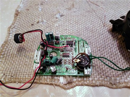
As mentioned I've already removed the Furby's brain and voice box.  I did think about if I could use all or part of the H-Bridge as a level shifter to pass the signals to the TB6612FNG board. However due to the tiny surface mounted resistors not really having appropriate values I decided instead to remove all of those transistors to avoid any unintended behaviour such as shorting the power rails. I also removed the wires for the back sensor as those were directly attached to the board rather than being jumpered. That allowed me to work on the board completely separate from the mechanics.

image


Power

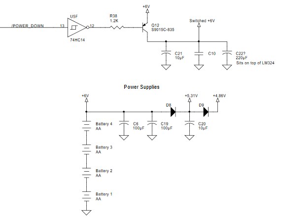
The Furby has a surprisingly sophisticated power setup. It has raw 6v from the batteries, 5.13v used by the main processor, 4.86v used by the EEPROM and a switched 6v used by the audio and IR sensors.

image

One thing that is missing from the schematic is what powers the 74HC14 which is used for the driving the LED and processing the opto-sensor signal. I checked and it was connect to the 6v line.


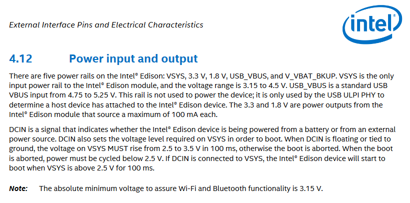
The Edison has an even more complex setup. The key thing here is that the 3.3v line can only source 100mA so I'd have to be very careful if I wanted to use that to drive any part of the Furby.

image

image


So my chosen approach is to power the Furby from its own battery connectors. The voltages will be slightly lower than design as I'm using a 5v supply rather than 6v but are still well within the range of the 74HC14 and sensor components.


The Edison will be powered from the J21 connector so that I can connect an audio card to the USB.


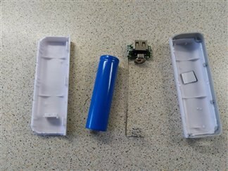
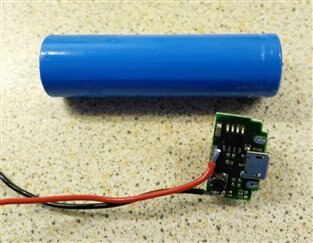
I've broken down a second powerbank into it's constituent components. It's interesting to see that there is just a single MP3401A chip and a few discrete components.

imageimage

Home Switch

The home switch is the simplest part of the circuit. I confirmed that one side was grounded and soldered a wire onto the COB header so that I could test it. To test, I added an LED and resistor connected to the positive supply.

image

LED

The LED for the opto-sensor is linked to the inverting buffer. I checked the schematic and the LED was connected to +Vcc but as suspected the orientation was reversed. I tried to get it to light and there was nothing so I pondered if it was an IR LED. So I soldered a second LED in parallel. This also produced no result (retrospectively this could be due to different junction voltages) so I unsoldered the original LED and replaced with a white LED. My theory was that the sensor might be only sensitive to a specific wavelength so the white would cover the most options, it also allowed be to visually check that it was on.


Phototransistor

The output of the phototransistor is fed into a Schmitt Trigger inverting buffer in the form of a 74HC14. The Schmitt trigger cleans up the signal to a nice square wave so it will be easy to detect a rising edge with the Edison. As suspected the schematic for the transistor was reversed.

To test the photo-transistor I wired an LED and resistor in series. The Furby was re-assembled and the slotted disk was rotated. The LED turned on and off as desired. When this is run from the motor it flashes faster than the eye can see so I'll have to ensure that the signals are processed fast enough.


You don't have permission to edit metadata of this video.
Edit media
x
image
Upload Preview
image


Motor

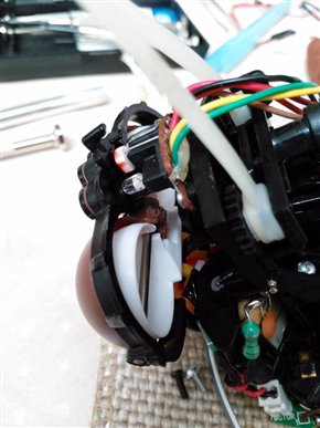
As mentioned the H-Bridge transistors were removed. This provided some spare sockets to attach a connector. A right angled connector was used as there was not a lot of vertical space. I plan to us the PWM option on the motor driver board so that the motor runs more slowly. The process for that is the same as [Upcycle It] Interactive Race Car Driver - Powering Motors


Eyelid Fix

Whilst testing the motor, I realised the eyelids on this Furby were closing but not re-opening, I discovered that the rubber coated cam was slipping on the back of the eyelids so I used a knife to score the plastic. That now works as correctly.
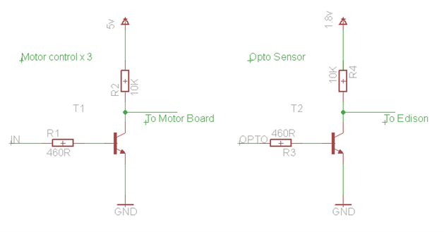
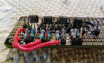
 

You don't have permission to edit metadata of this video.
Edit media
x
image
Upload Preview
image
image

Level Shifters

I soldered up my FRB590 transistors as per Harry Fairhead's suggestion in Exploring Edison - Life At 1.8V again using one of the scrapped Protozero boards.

image

image

Next Up

The driver is a complex part of the project so there's going to be another week of work on this. The main item is connecting up the sound to the Furby's speaker.


Reference

Hardware Guide for the IntelRegistered Edison Breakout Board

Hardware Guide for the IntelRegistered Edison Compute Module

Furby Schematic

Schmitt trigger design

Exploring Edison - Life At 1.8V (Harry Fairhead)


Previous Posts

Upcycle It Blogs tagged with upcycled_interactiveracecardriver

  • Sign in to reply

Top Comments

  • Workshopshed
    Workshopshed over 8 years ago in reply to jasonwier92 +6
    Thanks for the vote of confidence but as they say, "It's not over till the fat lady sings". There are many strong entries in this design challenge, and several like yourself with fully working projects…
  • Workshopshed
    Workshopshed over 8 years ago in reply to balearicdynamics +3
    Well, in that case, I'll just put my feet up and chill till the results come out.
  • balearicdynamics
    balearicdynamics over 8 years ago in reply to Workshopshed +1
    I should say that in tis challenge there are many ineresting projects but yours is the most complete respecting the directives you mentioned. Enrico
  • mcb1
    mcb1 over 8 years ago

    It is looking like you've solved some of the reasons it was discarded.

    Well done.


    All these UpcyleIt ideas are easier said than done.


    Hopefully those following the blogs have an appreciation of the time and skills needed to achieve the goal.

    There is software, mechanical, pcb, electronics, purchasing, design, and research with reverse engineering thrown in.


    Mark

    • Cancel
    • Vote Up +1 Vote Down
    • Sign in to reply
    • More
    • Cancel
  • mcb1
    mcb1 over 8 years ago in reply to Workshopshed

    I'll just put my feet up and chill till the results come out

    Good ... you'll have time to 3D print that blower then ... image

    • Cancel
    • Vote Up +1 Vote Down
    • Sign in to reply
    • More
    • Cancel
  • DAB
    DAB over 8 years ago

    Great update Andy.


    I think you made several smart decisions.

    Without knowing the details, bypassing the motor drive circuit was probably the correct move.

    Scoring the eyelid control wheel was an excellent quick fix.


    Taking extra care with the power distribution is a great idea.  I have run into these types of issues in the past and they can introduce some really weird symptoms.


    DAB

    • Cancel
    • Vote Up +1 Vote Down
    • Sign in to reply
    • More
    • Cancel
  • jasonwier92
    jasonwier92 over 8 years ago in reply to Workshopshed

    Oh no, you press on and make it even better. Nothing else, 3D print some flames!

    • Cancel
    • Vote Up +1 Vote Down
    • Sign in to reply
    • More
    • Cancel
  • Workshopshed
    Workshopshed over 8 years ago in reply to balearicdynamics

    Well, in that case, I'll just put my feet up and chill till the results come out. image

    • Cancel
    • Vote Up +3 Vote Down
    • Sign in to reply
    • More
    • Cancel
>
element14 Community

element14 is the first online community specifically for engineers. Connect with your peers and get expert answers to your questions.

  • Members
  • Learn
  • Technologies
  • Challenges & Projects
  • Products
  • Store
  • About Us
  • Feedback & Support
  • FAQs
  • Terms of Use
  • Privacy Policy
  • Legal and Copyright Notices
  • Sitemap
  • Cookies

An Avnet Company © 2025 Premier Farnell Limited. All Rights Reserved.

Premier Farnell Ltd, registered in England and Wales (no 00876412), registered office: Farnell House, Forge Lane, Leeds LS12 2NE.

ICP 备案号 10220084.

Follow element14

  • X
  • Facebook
  • linkedin
  • YouTube