element14 Community
element14 Community
    Register Log In
  • Site
  • Search
  • Log In Register
  • Community Hub
    Community Hub
    • What's New on element14
    • Feedback and Support
    • Benefits of Membership
    • Personal Blogs
    • Members Area
    • Achievement Levels
  • Learn
    Learn
    • Ask an Expert
    • eBooks
    • element14 presents
    • Learning Center
    • Tech Spotlight
    • STEM Academy
    • Webinars, Training and Events
    • Learning Groups
  • Technologies
    Technologies
    • 3D Printing
    • FPGA
    • Industrial Automation
    • Internet of Things
    • Power & Energy
    • Sensors
    • Technology Groups
  • Challenges & Projects
    Challenges & Projects
    • Design Challenges
    • element14 presents Projects
    • Project14
    • Arduino Projects
    • Raspberry Pi Projects
    • Project Groups
  • Products
    Products
    • Arduino
    • Avnet & Tria Boards Community
    • Dev Tools
    • Manufacturers
    • Multicomp Pro
    • Product Groups
    • Raspberry Pi
    • RoadTests & Reviews
  • About Us
  • Store
    Store
    • Visit Your Store
    • Choose another store...
      • Europe
      •  Austria (German)
      •  Belgium (Dutch, French)
      •  Bulgaria (Bulgarian)
      •  Czech Republic (Czech)
      •  Denmark (Danish)
      •  Estonia (Estonian)
      •  Finland (Finnish)
      •  France (French)
      •  Germany (German)
      •  Hungary (Hungarian)
      •  Ireland
      •  Israel
      •  Italy (Italian)
      •  Latvia (Latvian)
      •  
      •  Lithuania (Lithuanian)
      •  Netherlands (Dutch)
      •  Norway (Norwegian)
      •  Poland (Polish)
      •  Portugal (Portuguese)
      •  Romania (Romanian)
      •  Russia (Russian)
      •  Slovakia (Slovak)
      •  Slovenia (Slovenian)
      •  Spain (Spanish)
      •  Sweden (Swedish)
      •  Switzerland(German, French)
      •  Turkey (Turkish)
      •  United Kingdom
      • Asia Pacific
      •  Australia
      •  China
      •  Hong Kong
      •  India
      • Japan
      •  Korea (Korean)
      •  Malaysia
      •  New Zealand
      •  Philippines
      •  Singapore
      •  Taiwan
      •  Thailand (Thai)
      • Vietnam
      • Americas
      •  Brazil (Portuguese)
      •  Canada
      •  Mexico (Spanish)
      •  United States
      Can't find the country/region you're looking for? Visit our export site or find a local distributor.
  • Translate
  • Profile
  • Settings
Project Videos
  • Challenges & Projects
  • element14 presents
  • Project Videos
  • More
  • Cancel
Project Videos
Documents Build a Larson Scanner with Sound Using an ESP32 -- Episode 670
  • Documents
  • Members
  • Mentions
  • Sub-Groups
  • Tags
  • More
  • Cancel
  • New
Join Project Videos to participate - click to join for free!
Related
Recommended
Engagement
  • Author Author: cstanton
  • Date Created: 18 Jun 2025 4:36 PM Date Created
  • Last Updated Last Updated: 19 Jun 2025 12:07 PM
  • Views 31316 views
  • Likes 5 likes
  • Comments 31 comments

Build a Larson Scanner with Sound Using an ESP32 -- Episode 670

Join Mark as he builds a customisable Larson scanner using an ESP32, complete with synchronised Cylon-inspired sound effects. The project supports 12 to 50 WS2812 LEDs and uses four potentiometers to adjust brightness, speed, tail length, and LED count. Sound is driven by an I2S audio board and a surface-mounted speaker. It’s all powered via USB and programmed easily through a browser—no Arduino IDE needed. Perfect for cosplay, props, or unique lighting effects

Watch the Episode

You don't have permission to edit metadata of this video.
Edit media
x
image
Upload Preview
image

A Classic Effect with a Modern Upgrade

In this project, Mark builds a Larson scanner—an animated LED effect made famous by Knight Rider and Battlestar Galactica. Unlike many similar builds, this version includes synchronised sound effects, bringing an extra layer of authenticity to the visual sweep of the red “eye.” The project is customizable, allowing users to modify the number of LEDs used, brightness, animation speed, and tail length, making it suitable for a wide range of applications from cosplay to home decor.

image

ESP32 and Audio Integration

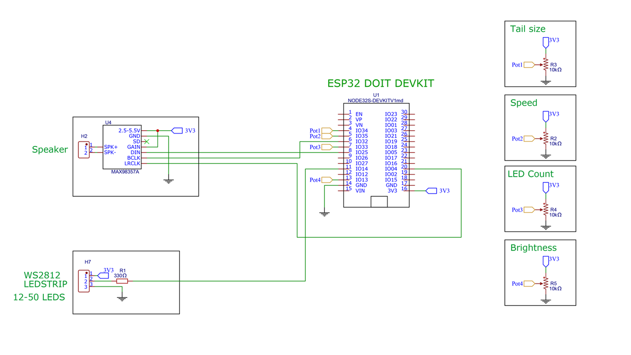
At the core of the build is an ESP32 development board—specifically one that supports dual-core processing. One core handles the LED animation, while the other plays the Cylon sound effect. The sound is generated through an I2S audio board connected to a speaker or speaker exciter, which vibrates a surface to act as a large resonating speaker. This unique approach allows for louder, more immersive sound without requiring a high-power amplifier.

image

LED Control and Hardware Configuration

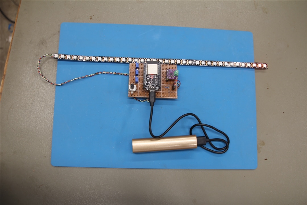
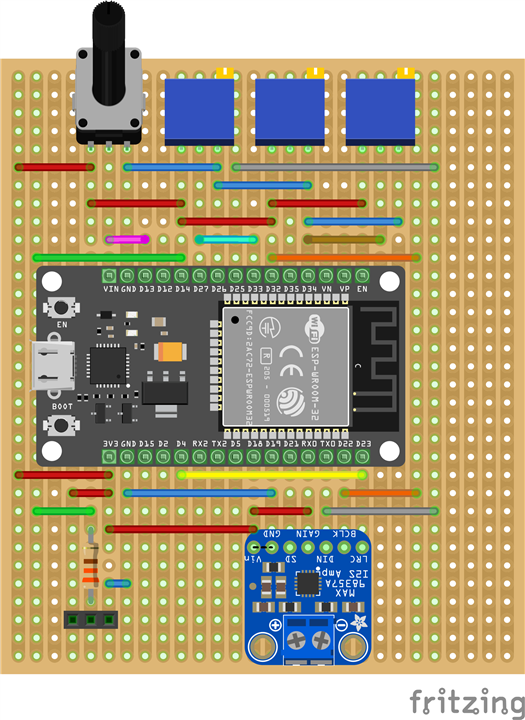
The LED output is controlled via a WS2812-compatible LED strip, which can range from 12 to 50 LEDs depending on availability and desired size. Four 10kΩ potentiometers are used to adjust the setup: one for brightness (marked with an 'X' for easier access), one to set the number of LEDs, one to control the sweep speed, and one to set the length of the light "tail" left behind during animation. A single 330Ω resistor is included in the circuit, and the assembly is built on a breadboard with standard wiring.

image

Browser-Based Programming and Setup

Programming the ESP32 is straightforward. The firmware can be installed directly via a web browser interface, avoiding the need for a traditional Arduino IDE setup. Once connected via USB, the board can be flashed using Chrome or Edge. The Arduino sketch provided below supports real-time configuration through the potentiometers, making fine-tuning immediate and easy without needing to recompile or reflash the firmware.

All Done!

With the added sound feature, this Larson scanner project offers a richer and more complete experience than LED-only versions. You could say, that it's fully KITT'ed out! If you build your own version or make modifications, share them in the comments below!

image

Supporting Files and Links

  • ESP32 Board Library
  • Web Based Flash Programming
  •  Episode 670 Resources 

Bill of Materials

Product Name Manufacturer Quantity Buy Kit
Trimmer multi turn 10Kohm Bourns 3 Buy Now
Potmeter 10K Alps Alpine 1 Buy Now
Exciter speaker 8 Ohm PUIaudio 1 Buy Now
Resistor 330 Ohm Multicomp 1 Buy Now
Socket 15 pin Harwin 2 Buy Now
Socket 6 pin Harwin 1 Buy Now
Pin header 6 pin Harwin 1 Buy Now
Pin header 15 pin Molex 3 Buy Now
Stripboard Kemo Electronic 1 Buy Now
Additional Parts
ESP32 DOIT DEVKIT 1,0
I2S Audio Board based on MAX98357
ledstrip WS2812 approx. 1 meter
 
  • led cosplay prop
  • prop
  • ws2812 led strip
  • i2s audio esp32
  • cylon eye build
  • sound reactive LEDs
  • cosplay
  • cosplaying
  • browser-based esp32 programming
  • larson scanner
  • diy cylon scanner
  • esp32 led project
  • surface speaker exciter
  • arduino larson scanner
  • friday_project
  • knight rider led effect
  • esp32 sound project
  • led animation with sound
  • friday_release
  • Share
  • History
  • More
  • Cancel
Actions
  • Share
  • More
  • Cancel
  • Sign in to reply

Top Comments

  • donnersm
    donnersm 6 months ago +3
    Feel free to ask any questions or leave comments. I'll be doing my best to answer as best as I can. :-)
  • beacon_dave
    beacon_dave 6 months ago +1
    Just need to 3D print the Pontiac Firebird Trans Am now... It might be worth adding an extra input selector so as you can change between different chase pattern effects.
Parents
  • AlaskaNick
    AlaskaNick 28 days ago

    Excellent project. Finally got all my parts in and routed out the copper. Wanted to confirm the top/bottom and left/right. At 4:23 you shows the copper routed out. Using the single notch at the bottom right, if I flip it over horizontally, that notch will be on the bottom left. Correct? Which way with the connector be on the ESP-32 be facing? Sorry for the questions. I am better at soldering the un-soldering.

    • Cancel
    • Vote Up 0 Vote Down
    • Sign in to reply
    • More
    • Cancel
  • beacon_dave
    beacon_dave 28 days ago in reply to AlaskaNick

    image

    • Cancel
    • Vote Up 0 Vote Down
    • Sign in to reply
    • More
    • Cancel
  • beacon_dave
    beacon_dave 28 days ago in reply to AlaskaNick

    Depends on which ESP32 devkit you are using, the pinouts are different.

    image

    • Cancel
    • Vote Up 0 Vote Down
    • Sign in to reply
    • More
    • Cancel
  • AlaskaNick
    AlaskaNick 28 days ago in reply to beacon_dave

    Video of board and esp32

    Dave I made a video of what I have.  I am still confused because my items are not lining up.  Let me know if the link does not work.  Thanks

    • Cancel
    • Vote Up 0 Vote Down
    • Sign in to reply
    • More
    • Cancel
  • beacon_dave
    beacon_dave 27 days ago in reply to AlaskaNick

    Your stripboard is the mirror image of what Mark's board above is. imageimage

    You'll either need to:

    1. solder the ESP32 onto the 'wrong side' of the board
      (space the header socket off the board enough to get your soldering iron tip under the black plastic.)
    2. spin the board around 180 and reuse the uncut tracks and bridge any cut ones that need bridging
    3. start over with a new board
    • Cancel
    • Vote Up 0 Vote Down
    • Sign in to reply
    • More
    • Cancel
  • beacon_dave
    beacon_dave 27 days ago in reply to AlaskaNick

    If you look closely at Mark's component layout diagram, you can see where he made the cuts to the tracks on the copper side.

    image

    • Cancel
    • Vote Up 0 Vote Down
    • Sign in to reply
    • More
    • Cancel
  • beacon_dave
    beacon_dave 27 days ago in reply to beacon_dave

    You could perhaps use a right-angle header as a 'surface mount'.

    image

    Just make sure they are spaced apart correctly before soldering.

    If you keep the pins facing each other under the ESP32, it will leave the holes free for the jumper wires. 

    • Cancel
    • Vote Up 0 Vote Down
    • Sign in to reply
    • More
    • Cancel
  • beacon_dave
    beacon_dave 27 days ago in reply to beacon_dave

    image

    • Cancel
    • Vote Up 0 Vote Down
    • Sign in to reply
    • More
    • Cancel
  • AlaskaNick
    AlaskaNick 27 days ago in reply to beacon_dave

    I will just get a couple more boards,  So if I route out the copper, as in in my picture, it should be good to go?image

    • Cancel
    • Vote Up 0 Vote Down
    • Sign in to reply
    • More
    • Cancel
  • beacon_dave
    beacon_dave 26 days ago in reply to AlaskaNick

    Yes, that is the copper side view.

    • Cancel
    • Vote Up 0 Vote Down
    • Sign in to reply
    • More
    • Cancel
  • AlaskaNick
    AlaskaNick 12 days ago in reply to beacon_dave

    I got the new boards in and made the appropriate slots.  Soldered everything in and tested it out.  The LEDs are working.  Made adjustments and that is working.  I just don't have any sound.  Tried 2 different speakers and no sound.  I am not using the PUI audio speakers but have 2 small speakers from I pulled out of some computers.  Not sure the watts on them. Do you think that could be the problem?  I did put a volt meter on it and plugged it on.  i couldn't find any connections that showed a volt running through them.  Would you give me a couple of connections to see if my solder joints are bad

    .image

    • Cancel
    • Vote Up 0 Vote Down
    • Sign in to reply
    • More
    • Cancel
  • beacon_dave
    beacon_dave 11 days ago in reply to AlaskaNick

    On the amplifier module you should be seeing 3V3 on both the Vin pin and the GAIN pin (via the two red wires).

    GND should be connected to the ESP32 GND (via the blue wire).

    DIN should be connected to the ESP32 pin D25 (via the two grey wires).

    BCLK should be connected to ESP32 pin D32 (via the two orange wires).

    LRC should be connected to D4 (via the yellow wire)

    Check that the copper tracks are cut between the sound module and the ESP module.

    Check ESP32 D32 has been cut between the ESP32 and the 5V supplying the middle pot.

    Check ESP32 D23 has been cut between the yellow wire and LRC (easy to miss that one)

    Looks like you can get more gain by adjusting the GAIN pin connection if needed: 

    image

    • Cancel
    • Vote Up 0 Vote Down
    • Sign in to reply
    • More
    • Cancel
Comment
  • beacon_dave
    beacon_dave 11 days ago in reply to AlaskaNick

    On the amplifier module you should be seeing 3V3 on both the Vin pin and the GAIN pin (via the two red wires).

    GND should be connected to the ESP32 GND (via the blue wire).

    DIN should be connected to the ESP32 pin D25 (via the two grey wires).

    BCLK should be connected to ESP32 pin D32 (via the two orange wires).

    LRC should be connected to D4 (via the yellow wire)

    Check that the copper tracks are cut between the sound module and the ESP module.

    Check ESP32 D32 has been cut between the ESP32 and the 5V supplying the middle pot.

    Check ESP32 D23 has been cut between the yellow wire and LRC (easy to miss that one)

    Looks like you can get more gain by adjusting the GAIN pin connection if needed: 

    image

    • Cancel
    • Vote Up 0 Vote Down
    • Sign in to reply
    • More
    • Cancel
Children
  • AlaskaNick
    AlaskaNick 11 days ago in reply to beacon_dave

    I got the sound to work!!!  But yes, it isn't that loud.  So if I understand your Table 8.  If I connect/route the 3v3 to the gain, I should get a louder volume?

    As yo can tell i am not fluent in Arduino.  Will you be adding other sound effects?  I was thinking of a random "By your command" 

    • Cancel
    • Vote Up 0 Vote Down
    • Sign in to reply
    • More
    • Cancel
  • beacon_dave
    beacon_dave 10 days ago in reply to AlaskaNick

    "...So if I understand your Table 8.  If I connect/route the 3v3 to the gain, I should get a louder volume?..."

    The GAIN pin should already be connected to Vin ( 3V3 ) via the red wire.

    Try disconnecting GAIN from 3V3 to see if you get an improvement; then connect GAIN to GND. Be careful that you don't short GND and Vin together.

    You could perhaps wire in a multipole switch with the common connected to the GAIN pin to allow you to easily select between the various options. You will need 2x 100k resistors.

    "...As yo can tell i am not fluent in Arduino..."

    Getting hands-on with projects like these and then trying to add new features, will help increase your experience.

    "...Will you be adding other sound effects?..."

    It's not my project, so I'll leave Mark to answer that one Slight smile

    "...I was thinking of a random "By your command" ..."

    Looks like that is already in the resource file provided above.

    • Cancel
    • Vote Up 0 Vote Down
    • Sign in to reply
    • More
    • Cancel
  • AlaskaNick
    AlaskaNick 10 days ago in reply to beacon_dave

    Attaching it to the GND did make it louder.  It's not like a KISS concert but louder than what it was before.  I see the resources with the sound files in it.  Could you direct me to a site that will teach me a little about combining two json files

    • Cancel
    • Vote Up 0 Vote Down
    • Sign in to reply
    • More
    • Cancel
  • beacon_dave
    beacon_dave 10 days ago in reply to AlaskaNick

    "...Attaching it to the GND did make it louder.  It's not like a KISS concert but louder than what it was before..."

    Looks like you get another 3dB yet if you connect to GND via a 100k resistor.

    • Cancel
    • Vote Up 0 Vote Down
    • Sign in to reply
    • More
    • Cancel
  • beacon_dave
    beacon_dave 10 days ago in reply to AlaskaNick

    "... Could you direct me to a site that will teach me a little about combining two json files..."

    There is a little intro to JSON here

    https://www.w3schools.com/js/js_json.asp

    • Cancel
    • Vote Up 0 Vote Down
    • Sign in to reply
    • More
    • Cancel
  • AlaskaNick
    AlaskaNick 9 days ago in reply to beacon_dave

    It work.  Did get a little bit more sound out of it.  Sounds better

    • Cancel
    • Vote Up 0 Vote Down
    • Sign in to reply
    • More
    • Cancel
  • AlaskaNick
    AlaskaNick 9 days ago in reply to beacon_dave

    UGH!! Back to school Stuck out tongue winking eye

    • Cancel
    • Vote Up 0 Vote Down
    • Sign in to reply
    • More
    • Cancel
  • beacon_dave
    beacon_dave 9 days ago in reply to AlaskaNick

    Looks like there is also an audio volume setting in the code:

    image

    • Cancel
    • Vote Up 0 Vote Down
    • Sign in to reply
    • More
    • Cancel
  • AlaskaNick
    AlaskaNick 6 days ago in reply to beacon_dave

    OK.  I must be looking at something totally different.  When I do a search through what I believe is the source code.  I do not see any audio listings.  I am opening the ESP32 board library in Google.  I can see what looks to be programming.  It's has been years.  Did some programming in Pascal and C but this doesn't look anything like it.

    • Cancel
    • Vote Up 0 Vote Down
    • Sign in to reply
    • More
    • Cancel
  • beacon_dave
    beacon_dave 6 days ago in reply to AlaskaNick

    image

    Try looking in the program sketch file: Cylon.ino

    • Cancel
    • Vote Up 0 Vote Down
    • Sign in to reply
    • More
    • Cancel
element14 Community

element14 is the first online community specifically for engineers. Connect with your peers and get expert answers to your questions.

  • Members
  • Learn
  • Technologies
  • Challenges & Projects
  • Products
  • Store
  • About Us
  • Feedback & Support
  • FAQs
  • Terms of Use
  • Privacy Policy
  • Legal and Copyright Notices
  • Sitemap
  • Cookies

An Avnet Company © 2025 Premier Farnell Limited. All Rights Reserved.

Premier Farnell Ltd, registered in England and Wales (no 00876412), registered office: Farnell House, Forge Lane, Leeds LS12 2NE.

ICP 备案号 10220084.

Follow element14

  • X
  • Facebook
  • linkedin
  • YouTube