

In the first part of this introduction to robotics, Miloš Rašić focused on the foundations of building a robot, covering electronics, mechanics, sensors, actuators and microcontrollers. In this second instalment, the focus shifts to the software side of robotics and the control systems that bring mechanical hardware to life.
Rather than looking at robotics as a collection of disconnected components, Miloš begins by showing how software and hardware fit together into a complete robotic system. From low-level motor control to high-level path planning and Robot Operating System (ROS) development, each layer plays a different role and often runs on different hardware.
Watch now
If you missed the first part of this introduction to robotics, you can find it here:
Building the Foundations of Your First Robot - An Introduction to Robotics
Robot Software Architecture
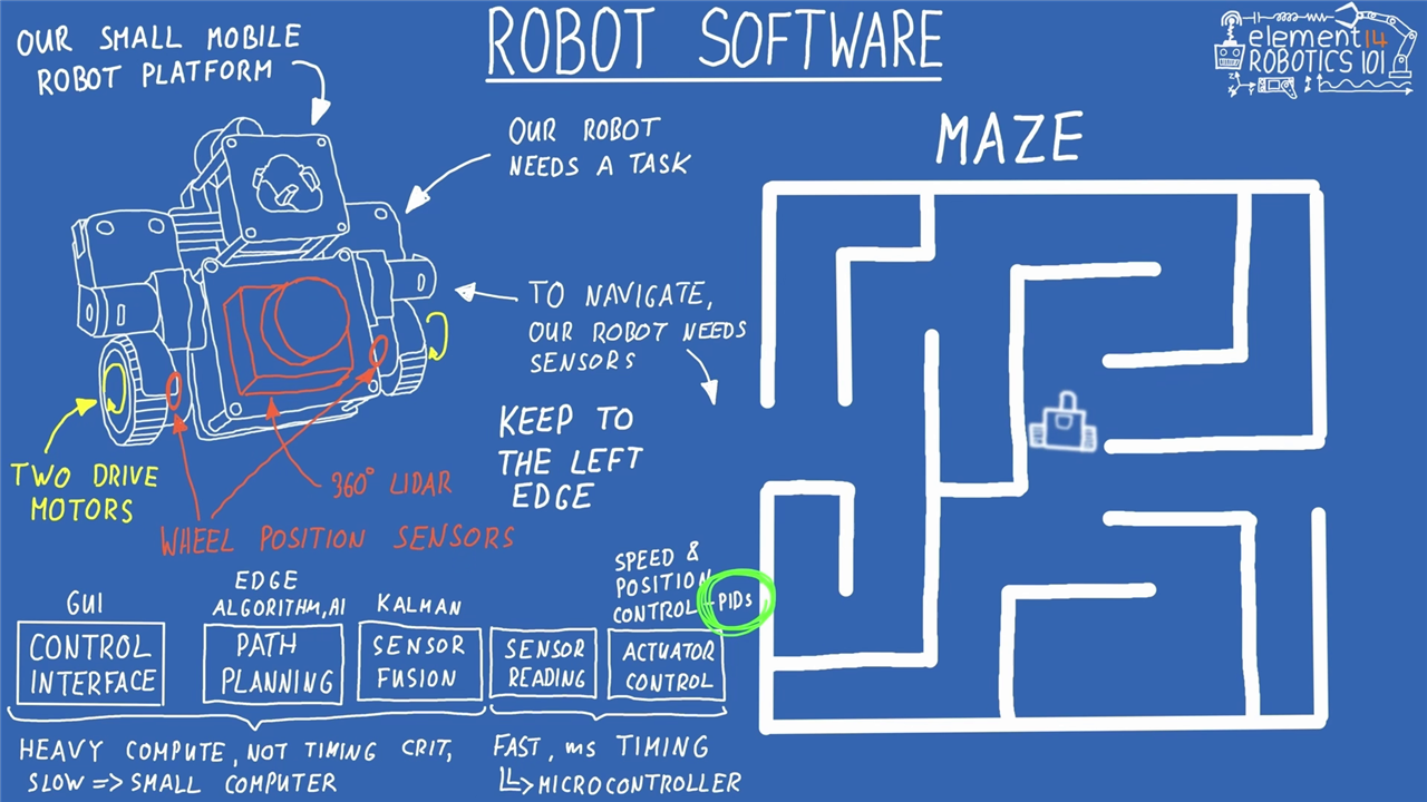
Having already explored robot hardware, Miloš starts by looking at a simple mobile robot platform from a software perspective. The example robot uses a differential drive system with two powered wheels, but the concepts apply equally well to robot arms, autonomous vehicles and more advanced mobile platforms.
To explain how the different software layers fit together, he demonstrates a classic robotics task: maze navigation. A robot attempting to navigate from one point to another must first understand its surroundings, determine how it should move, and then translate those decisions into precise motor commands.
For sensing, Miloš equips the example robot with wheel encoders and a 360-degree LIDAR. The wheel encoders provide position and speed information, while the LIDAR measures obstacles throughout the robot's surroundings.
“To pull this off the robot needs some sensors to figure out where the obstacles are. For example we can use two wheel position sensors called encoders so we can measure the robot's position and speed and a 360 degree LIDAR sensor to measure the distance to the obstacles.”
Once those sensors are available, the robot's software can be divided into several distinct layers:
- Control Interface – a graphical interface or control application used to interact with the robot.
- Path Planning – navigation logic or AI that determines where the robot should go.
- Sensor Fusion – combining information from multiple sensors to improve accuracy.
- Sensor Acquisition – collecting data from encoders, LIDARs and other sensors.
- Actuator Control – controlling motors and other outputs.
Miloš highlights that not all software tasks should run on the same hardware. Higher-level tasks such as path planning, user interfaces and sensor fusion require comparatively large amounts of processing power but generally do not require microsecond timing precision.
“The higher level tasks, the interface, pathfinding and fusion require heavy computing power. They process a lot of data slowly and are not strictly timing critical.”
These processes are ideally suited to single-board computers such as a Raspberry Pi or NVIDIA Jetson.
Low-level control is very different. Reading sensor signals, generating motor control outputs and running closed-loop control algorithms requires highly deterministic timing.
“Reading raw electrical signal and pushing power to motors requires lightning fast millisecond level precision.”
This is why robotics systems frequently combine a microcomputer with one or more microcontrollers. The microcomputer performs the computationally intensive tasks, while the microcontroller handles time-critical operations such as motor control loops.
Anyone new to embedded systems may find it useful to supplement this section with element14's guide to The Basics of Microcontrollers, as well as the broader resources available through the element14 Learning Center.
PID Controllers
Once software responsibilities have been divided between the microcomputer and microcontroller, the next challenge is moving the robot accurately.
At the heart of most robotic motion systems sits a PID controller.
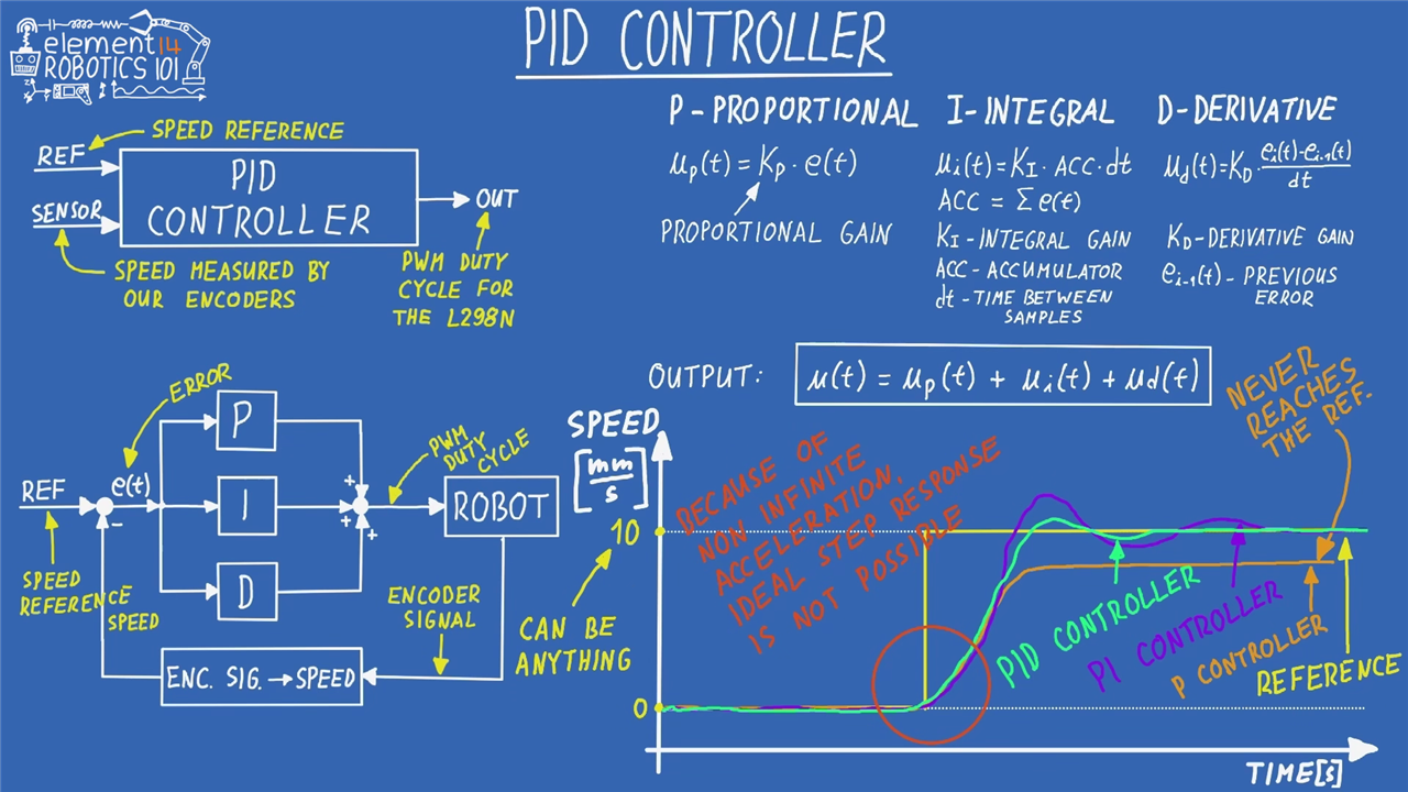
PID stands for Proportional, Integral and Derivative, and Miloš describes it as one of the most important concepts in robotics and control engineering. Whether controlling wheel speed, robot arm joints or industrial machinery, PID control is used extensively because of its ability to minimise error between the desired behaviour and the actual behaviour.
“PID is very, very important.”
Using a brushed DC motor, magnetic encoder and a custom dual motor driver PCB, Miloš demonstrates how each part of the controller contributes to system behaviour.
The controller receives two key inputs:
- A reference value (the target speed or position).
- A measured value from a sensor.
The difference between the two becomes the control error.
“The idea and the purpose of the PID controller is to actually minimise that error, ideally to have it at zero.”
Proportional Control
The proportional term increases output in proportion to the current error.
Miloš uses a driving analogy to explain the concept. If a car is travelling at 50 km/h but the desired speed is 100 km/h, the driver naturally applies more throttle than they would when travelling at 95 km/h.
The larger the error, the stronger the corrective action.
However, proportional control alone often leaves a steady-state error. The motor approaches the target but never quite reaches it.
Integral Control
The integral term accumulates error over time.
If a system continually falls slightly below the desired value, the integral term gradually increases the output until the remaining error disappears.
“The integral part will get you just right around to the 100.”
During the demonstration, Miloš shows how adding integral gain gradually removes the offset that remains when only proportional control is used.
Derivative Control
The derivative term looks at how quickly the error is changing.
Its role is to help prevent overshoot and improve stability.
In theory, derivative control can significantly improve system response, but Miloš also points out that practical implementations are not always straightforward.
“Putting any derivative into this system will just make it really really noisy so I decided to keep it at zero.”
This is a useful reminder that theory and real hardware frequently behave differently. Sensors introduce noise, and every system has limitations that influence how aggressively a controller can be tuned.
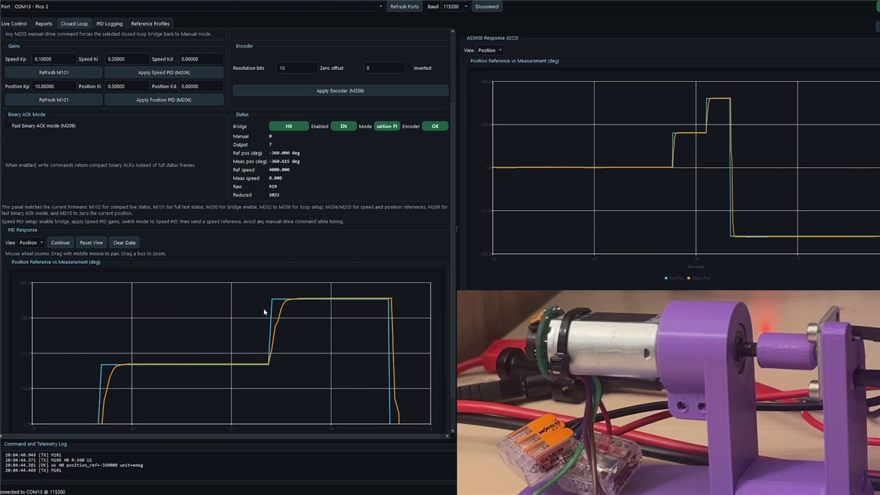
Throughout the demonstrations, Miloš repeatedly returns to the process of tuning gains and observing the resulting behaviour. Overshoot, oscillation, noise and settling time all become visible when viewing the live response graphs generated through the custom software interface.
Readers interested in motors and drive systems may wish to explore element14's detailed guide to Motor Control: Motor Drive Control for Makers, along with Magnetic Encoders, both of which expand on technologies featured in this project.
Motion Profiles: Bringing Theory Into Reality
Even the best-tuned PID controller cannot achieve the impossible.
One of the key lessons Miloš introduces is the difference between mathematical idealism and physical reality.
When drawing references on paper, it is tempting to command a motor to jump instantly from one speed or position to another. In practice, this cannot happen.
“Nothing infinite is possible when it comes to those physical things.”
Using the familiar example of driving past a speed limit sign, Miloš explains why acceleration must always occur over time.
If a vehicle instantaneously changed from 50 km/h to 80 km/h, the required acceleration would become infinite because the velocity change would occur over zero time.
The same limitation exists in robotic systems.
When a square-wave reference is sent to a motor, even a well-tuned control system cannot follow the command perfectly. The motor's acceleration limits prevent it from instantly reaching the new target.
“No sudden changes are possible in the real world.”
This leads to the concept of motion profiling.
Miloš compares three common reference profiles:
- Step profiles — mathematically simple but physically impossible to follow accurately.
- Trapezoidal profiles — significantly better because acceleration is finite.
- S-curve profiles — smoother acceleration transitions and more realistic robot motion.
The trapezoidal profile improves performance by gradually ramping velocity up and down, but abrupt changes in acceleration still occur at the corners.
The S-curve profile goes one stage further by smoothing those transitions.
“To get a truly smooth realistic movement we use an S profile.”
The practical demonstrations show the difference clearly. Square-wave references create large tracking errors. Trapezoids improve behaviour, while S-curves allow the motor to follow the command much more closely.
Throughout the tests, Miloš reinforces the idea that the objective is not perfect mathematical tracking but achieving motion that remains inside the physical limits of the system.
“The whole idea is to get these two to match so that you can't tell them apart.”
He also notes that filtering recorded trajectories and removing sharp edges can significantly improve motion quality in future robotics projects.
Power delivery and motor capability have a major influence on achievable motion profiles, making the element14 resources on Power Essentials for Makers and motor control particularly useful companion reading.

Robot Operating System (ROS)
After covering low-level control, Miloš moves to high-level robotics software and introduces the Robot Operating System, or ROS.
Rather than serving as a conventional operating system, ROS acts as a middleware framework that simplifies the process of building modular robotic software.
“It's not an actual operating system but it's a really nice framework for developing robotics projects.”
Modern robotics projects often contain many independent subsystems. Sensors, motor controllers, navigation algorithms, vision systems and user interfaces all need to communicate while remaining maintainable.
ROS addresses this challenge through a node-based architecture.
“ROS allows us to write small independent modules of code called nodes.”
Each node performs a specific role. One node might communicate with a motor controller, another might process sensor data, and another could implement navigation logic.
These nodes exchange information using ROS topics.
Miloš describes topics as communication channels that allow nodes to publish and subscribe to messages. Nodes can listen to data streams from multiple sources while simultaneously publishing their own outputs.
ROS also supports services for one-time interactions.
Unlike topics, which continuously transport data, services provide request-and-response communication.
“Topics are expected to come at a certain rate continuously, while for service calls they are ad hoc and are also followed by a response.”
To illustrate the advantages of this architecture, Miloš returns to the maze-solving robot. One navigation node implements a left-wall-following algorithm. By replacing it with another node that follows the right-hand wall, the robot completely changes its behaviour.
The lower-level motor and sensor nodes remain untouched.
“We don't have to rewrite a single line of our motor controller or PID code.”
This modularity is one of the main reasons ROS has become widely adopted throughout the robotics industry.
For newcomers who want to begin learning ROS in a structured way, element14's Essentials of Robot Operating System 2 provides an excellent companion resource and introduces topics such as nodes, topics, services and ROS application development in more detail.
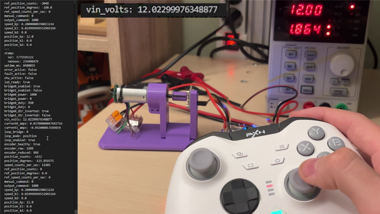
Miloš even demonstrates ROS 2 Humble running on a Raspberry Pi 4, with nodes communicating between an Xbox-style controller, a custom motor driver board and the motor itself. Through ROS, telemetry data including voltage, current and encoder position is streamed directly to the system while live commands control the motor.
The demonstration neatly ties together the themes introduced throughout this episode. High-level software runs on the Raspberry Pi, while low-level control remains the responsibility of dedicated hardware designed to respond with the speed and determinism that robotics applications require.
Where the Journey Continues
By the end of this part, the complete software stack of a robot begins to take shape. Sensors collect information, controllers process it, motion profiles create achievable trajectories, and ROS ties the entire system together into a modular framework.
As Miloš explains, understanding these concepts is enough to begin building genuinely capable robotic systems, even using simple materials and approachable hardware.
“If you just have a hot glue gun and a piece of cardboard you'll be able to follow along.”
The next parts in the series take these ideas and apply them to real robot builds, demonstrating how control engineering, motion planning and software architecture combine to create working robotic platforms.
Be sure to follow along for further introductions to robotics with Miloš.
