I decided to make a Maneki Neko for the Project14 Op-Amp-a-Palooza contest. And it has a laser.

Maneki Neko translates literally as “Beckoning Cat” from Japanese. One story is that a cat raised its paw as if to beckon a traveler away from under a tree just as lightning struck, thus saving them. The paw being raised and the color has different meanings in Japan. A white cat means good luck, and if the paw on the left is raised it is welcoming. Raising the paw on the right brings money and Maneki Neko is often seen in shops.
You may be asking yourself why build a Maneki Neko and what does it have to do with op-amps? Well, it is about cats which is reason enough in and of itself. And this Maneki Neko will rotate while dancing a laser on the wall to entertain cats. As for op-amps, the animating servos are driven by PWM using circuits with op-amps.
Overview
The simplified block diagram below shows the major parts of the build.

The Maneki Neko shown on the right holds a red laser of the type used by pointers with a resistor in series to limit current. The beckoning arm is powered by a small SG90 servo and another SG90 rotates the cat on the base. The electronics that drive the servos fit into the base and the major sub-circuits are shown in boxes on the left side of the diagram.
There are separate voltage-controlled driver boards for each servo as shown in the middle of the diagram. Each has two dual-channel op-amps that generate the pulses necessary to drive the servos. The pulse duration and thus servo rotation is controlled by varying the input voltage to the circuit.
The board supplying the input provides separate voltages for the beckoning and rotation servo drivers as seen in the furthest left box of the diagram. Two NE555 timers set the frequency of rotation followed by simple low-pass filters and op-amps to condition the output.
Additional detail on the major sub-components is given below.
Voltage Controlled Servo Driver
The circuit that outputs PWM for controlling the servos is described by w2aew in this post #186: Circuit Fun: Control an RC Servo with an adjustable DC voltage. The schematic below shows how it was implemented for this project.

The circuit works by creating a triangle wave and then using a comparator to clip the triangle into a pulse.
To understand how the circuit works, start by looking at the Triangle Generator at the top of the schematic. The frequency needs to be in the range of 30 to 50 Hz for a hobby servo. The circuit requires a rail to rail op-amp, here the dual-channel TL972IP is used. U1B is an integrator and U1A is a hysteresis comparator. The inverting pin on U1A and the non-inverting pin on U1B are fixed by the reference voltage in the box far right top which is set at one-half Vcc, in this case, 2.5V.
Assume that the output to U1A is low to start. Then the non-inverting pin on U1B is higher than the inverting pin and the output will begin to rise as it charges C1. When the voltage is higher than the reference voltage it will cause U1A state to change state. At that point, the output from U1B will go low and cause C2 to discharge. This oscillation with an integrator ramping up and down gives a triangle wave. An oscilloscope screenshot is shown below.

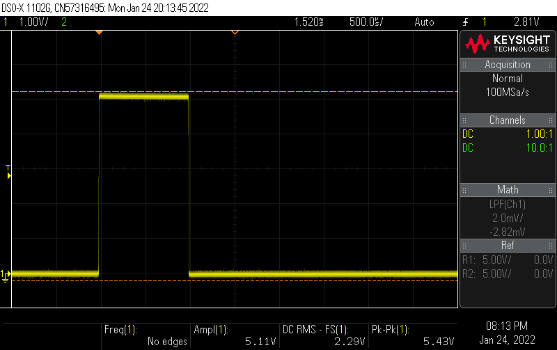
The triangle wave is fed to the box labeled PWM output which has another TL972IP acting as a comparator. The 100k resistor provides some positive feedback to give some hysteresis to prevent chattering of the servos. The voltage input to the inverting pin is kept relatively high on U2B but can be varied to create a pulse length between 1 to 2 ms to control a servo. In the screenshot below a 5V, 1 ms pulse is created at the 34.2Hz frequency from the triangle wave.

The last part of the circuit of interest is in the box labeled conditioning. Because the pulse is quite short the voltage required to clip the triangle wave occurs over a narrow range near the peak of the triangle. The conditioning circuit takes a 0 to 5V input and turns it into the voltage required to snip off the top of the triangle wave.
Resistors R1 and R2 attenuate the 0 to 5V input down to approximately 0 to 0.15V. Op-amp U2A buffers the voltage from the divider while R6 and R8 provide an offset to move the output towards the top of the triangle wave.
For a thorough and easier-to-follow description of the circuit watch the video by w2aew linked above.
The schematic was used to create the PCB shown below in KiCad 6.

One of the objectives was to learn some of the new features in KiCad 6. Separate blogs were made on some of the features such as the Servo Logo on the PCB and are linked at the end of this post.
I often breadboard circuits before sending them off for a PCB but in this case, did not. In the past, I’ve suffered mightily by building something like this that didn't work and then going through painful debugging trying to find the issue. To avoid this, a plan was made up beforehand to build out the circuit section by section testing as it was built. The plan is shown below.

The plan was blogged separately, along with several other start-up tips from element14 members here. Fortunately, this circuit worked the first time it was tested. The short video below demonstrates driving a servo and shows the pulse on the oscilloscope as the input control voltage is varied manually.
Dual-Channel Triangle Wave Generator
The following criteria were considered for selecting the control voltage circuit:
- Period must be easily set in the range of 1 to 3+ seconds
- Voltage range will vary between the two servos
Several circuits were tried but in the end, a 555 timer was chosen to set the period with a simple low pass filter to smooth the rough edges. I’m calling it a triangle wave, but it is cruder than that. The schematic is shown below.

The table below the schematic was done to assure the period could be set with the components at hand. The values for the low pass filter were guesses to give an RC constant in a range that would give a smooth transition of adequate duration but tweaking was expected. The resistor R4 forms a voltage divider with R3 to give offset.
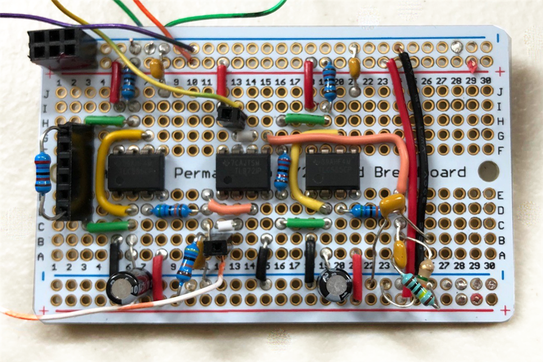
The circuit was soldered up on a prototyping board with two channels. Several caps and resistors were bodged in to get it to work as desired.

One channel operating is shown in the video below.
The oscilloscope shows the voltage output in yellow and the PWM in green.
Maneki Neko
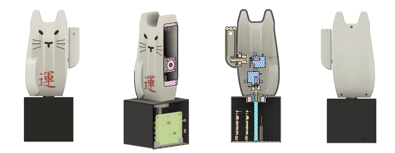
The Maneki Neko is an original design that was sketched out and scaled to just fit on my Anycubic I3 Mega in Fusion 360. The images below show various views with cutaway sections.

Design features include:
- Printed in PLA
- Reduced friction using bearings on the base and moving arm
- Embossed facial features and Kanji character for “luck”
- Embossed features painted with fingernail polish
- Removable electronic card mounted in the base
- Hidden wiring designed to pass through the rotating connections

The use of nail polish was a neat trick I’ll repeat. It doesn’t run or drip and is easy to apply and looks good. Because the body was printed face up to get the desired embossing there was a considerable amount of support material to be removed as designed but this went OK. I would consider printing the face separately in the future to avoid the support. Because it was a large print there was some warping but not too noticeable. KiCad 6 models were exported to Fusion 360 using the method I blogged about and inserted in the supporting links below.

Electronic Assembly
The electronic assembly went together easily and was tested outside the Maneki Neko before mechanical assembly. Considerable tweaking, bodging, and testing were required to get close to the movement desired.

Mechanical Assembly
There was some difficulty with the mechanical assembly in that one of the servo mounts broke due to the laminations from the way it was printed and the design. Both motor mounts were removed, the base plastic smoothed by scraping, and new larger ones fitted and glued in place with epoxy. In the image below shown before assembly the flanged bearing used for the base is visible. A smaller skateboard bearing was used for the arm. Both the back of the cat and the bottom of the base are attached with 3mm screws into heat-set inserts.

Demonstration
The video below shows the final working project.
Conclusion
Several improvements were mentioned in the write-up but the single biggest improvement would be to not use these circuits to drive servos – use a microcontroller! They are cheaper, smaller, and much more easily programmed to perform the desired actions. It would even be possible to use a radio / WiFi link to a smartphone or tablet to control different behaviors wirelessly.
It works OK but hasn’t been tested with cats yet to see if they are interested in chasing the laser. I expect there is too much movement and further tweaking needed. Ideally, this would be done externally with potentiometers but I needed to finish the project before the weekend.
Having said that, this was a lot of fun and I learned a lot. It incorporates op-amps used as integrators, oscillators, comparators, offset amplifiers, and buffers.
I hope you enjoyed this project and thanks for reading! Comments and suggestions are always welcome. The links below give additional detail on portions of the project not detailed in this post.
Links to Supporting Posts
KiCad 6 – Populating a PCB using the Interactive HTML BOM Plugin
Powering Up and Debugging PCB Prototypes

Top Comments
-

rsjawale24
-
Cancel
-
Vote Up
0
Vote Down
-
-
Sign in to reply
-
More
-
Cancel
-

fmilburn
in reply to rsjawale24
-
Cancel
-
Vote Up
0
Vote Down
-
-
Sign in to reply
-
More
-
Cancel
Comment-

fmilburn
in reply to rsjawale24
-
Cancel
-
Vote Up
0
Vote Down
-
-
Sign in to reply
-
More
-
Cancel
Children