element14 Community
element14 Community
    Register Log In
  • Site
  • Search
  • Log In Register
  • Members
    Members
    • Benefits of Membership
    • Achievement Levels
    • Members Area
    • Personal Blogs
    • Feedback and Support
    • What's New on element14
  • Learn
    Learn
    • Learning Center
    • eBooks
    • STEM Academy
    • Webinars, Training and Events
    • More
  • Technologies
    Technologies
    • 3D Printing
    • FPGA
    • Industrial Automation
    • Internet of Things
    • Power & Energy
    • Sensors
    • More
  • Challenges & Projects
    Challenges & Projects
    • Design Challenges
    • element14 presents
    • Project14
    • Arduino Projects
    • Raspberry Pi Projects
    • More
  • Products
    Products
    • Arduino
    • Dev Tools
    • Manufacturers
    • Raspberry Pi
    • RoadTests & Reviews
    • Avnet Boards Community
    • More
  • Store
    Store
    • Visit Your Store
    • Choose Another Store
      • Europe
      •  Austria (German)
      •  Belgium (Dutch, French)
      •  Bulgaria (Bulgarian)
      •  Czech Republic (Czech)
      •  Denmark (Danish)
      •  Estonia (Estonian)
      •  Finland (Finnish)
      •  France (French)
      •  Germany (German)
      •  Hungary (Hungarian)
      •  Ireland
      •  Israel
      •  Italy (Italian)
      •  Latvia (Latvian)
      •  
      •  Lithuania (Lithuanian)
      •  Netherlands (Dutch)
      •  Norway (Norwegian)
      •  Poland (Polish)
      •  Portugal (Portuguese)
      •  Romania (Romanian)
      •  Russia (Russian)
      •  Slovakia (Slovak)
      •  Slovenia (Slovenian)
      •  Spain (Spanish)
      •  Sweden (Swedish)
      •  Switzerland(German, French)
      •  Turkey (Turkish)
      •  United Kingdom
      • Asia Pacific
      •  Australia
      •  China
      •  Hong Kong
      •  India
      •  Korea (Korean)
      •  Malaysia
      •  New Zealand
      •  Philippines
      •  Singapore
      •  Taiwan
      •  Thailand (Thai)
      • Americas
      •  Brazil (Portuguese)
      •  Canada
      •  Mexico (Spanish)
      •  United States
      Can't find the country/region you're looking for? Visit our export site or find a local distributor.
  • Translate
  • Profile
Electromagnetism
  • Challenges & Projects
  • Project14
  • Electromagnetism
  • More
  • Cancel
Electromagnetism
Blog 3000A clamp table and amplifier update #2
  • Blog
  • Forum
  • Documents
  • Events
  • Members
  • Mentions
  • Sub-Groups
  • Tags
  • More
  • Cancel
  • New
Electromagnetism requires membership for participation - click to join
Blog Post Actions
  • Subscribe by email
  • More
  • Cancel
  • Share
  • Subscribe by email
  • More
  • Cancel
Group Actions
  • Group RSS
  • More
  • Cancel
Engagement
Author: three-phase
Date Created: 15 Apr 2019 8:11 PM
Views: 167
Likes: 5
Comments: 4
  • clamp adapter table
  • electromagnetismch
  • flir cm55
  • current amplifier
  • impedance measurements
  • clamp meter
Related
Recommended

3000A clamp table and amplifier update #2

three-phase
three-phase
15 Apr 2019

I have done some more work today on the current amplifier and found that I did not have the input turned up to a high enough voltage to obtain the full 1A output, so I have now repeated the test and monitored the heat output from the amplifier.


This is still just within the nominal operating temperature specified for the op-amp, but it was still climbing slowly when turned off. When switched back down to a 0.5A output, the temperature does start to drop away quite rapidly.


With this completed, I decided to do a few quick tests with a 20 turn coil and a CM55 current clamp as shown below.


{gallery} CM55 current clamp tests

10A reading expected on clamp meter

20A reading expected on clamp meter

Clamp meter taken beyond frequency specification

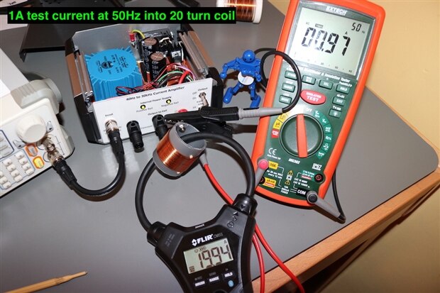
The first two tests show the clamp meter with the expected readings for a 50Hz input into the 20 turn coil. The frequency was then raised in the third picture and you can see that the current reading drops right off. For a Rogowski style clamp, the CM55 actually has quite a poor bandwidth.


My next stage with the current amplifier will be to try and figure out a way of measuring the input and output of the coils with the equipment I have, to see if there is any frequency drop off across the coil.


I have collected some impedance data for each of the coils I have wound using an LCR meter.


The data shows the increasing impedance of the coil as the frequency is increased. This may give issues with being able to reach the full output current using the existing amplifier design.

Anonymous

Top Comments

  • shabaz
    shabaz over 3 years ago +3

    Hi Donald,


    This is a great project, a nice challenge. I was wondering, (these ideas may have flaws..): if the coil could be possible with copper blanks per turn (e.g. like these) with the centre punched…

  • genebren
    genebren over 3 years ago +3

    Donald,


    Another great update.  It does appear that the clamp is rolling off at higher frequencies.  Looking at the specification for the clamp, the AC frequency range is listed as 45 - 500Hz, so 5KHz is out…

  • three-phase
    three-phase over 3 years ago in reply to shabaz +1

    That is an interesting alternative to manufacturing a coil, depending on the size of the copper, each joint is going to have be either soldered or brazed, there will also need to be insulation between…

  • three-phase
    three-phase over 3 years ago

    Many thanks Gene. I did go and check the frequency response of the CM55 myself and it did surprise me how low it was. The older style tongue clamps did have a low frequency response due to the limitations of the magnetic circuit and the introduction of Rogowski coils provided a much higher frequency capability.


    The Fluke i2000 I have will go up to 20kHz, so it must be a design choice by Flir to reduce the frequency capability within the electronics.


    Kind regards.

    • Cancel
    • Up +1 Down
    • Reply
    • More
    • Cancel
  • three-phase
    three-phase over 3 years ago in reply to shabaz

    That is an interesting alternative to manufacturing a coil, depending on the size of the copper, each joint is going to have be either soldered or brazed, there will also need to be insulation between each turn to prevent the turns from shorting out.


    Unfortunately there is a compromise in all designs and I would need at least a 25mm diameter bore to be able to get the larger Rogowski coils through the test coil. If the coil gets too long, then again I may not be able to get the clamp to fit.


    The formers I am using at the moment are just leftover bits of 40mm waste pipe and couplers as I couldn't find anything else suitable around the house. I have some 22mm plastic water pipe which the small clamp meter will fit through, but the larger one wouldn't, so I didn't use that.


    The parallel operation of the op-amps is interesting, I did think of that, but wondered what the consequences would be with regard to synchronisation and feedback within the op-amp. I have some spare PCBs, so will perhaps build them up and see what happens. The problem then will be having a coil that can take the increased current, which means increasing the size of the magnet wire. The thicker the magnet wire gets, the harder it is to manipulate and make into smaller sized coils.


    Plenty to ponder about whilst I search for some smaller formers.


    Thanks for your comments, very helpful as usual.


    Kind regards.

    • Cancel
    • Up +1 Down
    • Reply
    • More
    • Cancel
  • genebren
    genebren over 3 years ago

    Donald,


    Another great update.  It does appear that the clamp is rolling off at higher frequencies.  Looking at the specification for the clamp, the AC frequency range is listed as 45 - 500Hz, so 5KHz is out of range.  I do remember that many of the clamps that I have worked with in the past did have rather narrow frequency ranges.


    The impedance of your coil does make it look like the amplifier might have trouble driving it at higher frequencies.


    Keep up the good work!


    Gene

    • Cancel
    • Up +3 Down
    • Reply
    • More
    • Cancel
  • shabaz
    shabaz over 3 years ago

    Hi Donald,


    This is a great project, a nice challenge. I was wondering, (these ideas may have flaws..): if the coil could be possible with copper blanks per turn (e.g. like these) with the centre punched out and disposed, and then a slit cut, and then bent into a coil to attach to the next one. I can't figure out how to bond each one though.. maybe lapped slightly and soldered. Then, maybe the diameter can be smaller, to reduce inductance, with the larger rim of the blanks dissipating heat. However perhaps it wouldn't help, if the design ends up being too long (since the copper blank method wouldn't have an inner coil like you have implemented with wire). Or maybe a paralleled-up op-amp method for passing even higher current, reducing the number of turns.

    • Cancel
    • Up +3 Down
    • Reply
    • More
    • Cancel
Element14

element14 is the first online community specifically for engineers. Connect with your peers and get expert answers to your questions.

  • Members
  • Learn
  • Technologies
  • Challenges & Projects
  • Products
  • Store
  • About Us
  • Feedback & Support
  • FAQs
  • Terms of Use
  • Privacy Policy
  • Legal and Copyright Notices
  • Sitemap
  • Cookies

An Avnet Company © 2022 Premier Farnell Limited. All Rights Reserved.

Premier Farnell Ltd, registered in England and Wales (no 00876412), registered office: Farnell House, Forge Lane, Leeds LS12 2NE.

ICP 备案号 10220084.

Follow element14

  • Facebook
  • Twitter
  • linkedin
  • YouTube