


Introduction
Back in summer 2022, there was an IOLink quiz that had an associated MAX32666FTHR board prize. I was thrilled to be selected and after a bit of delivery ordeal, I received it in October of the same year.
Since then, I had various ideas for it, like a vibration logger to detect when water is flowing in the main pipe entering the house, but communication via Bluetooth felt foreign to me, where I’m used to ZigBee devices being connected to a zigbee2mqtt instance.
As a result, it was left sitting in the “boards” bin for better days, and hopefully, it came back to light in less time than the 15 years it took to revive my AT PSU project.
Indeed, with an accelerometer, quite a lot of flash and RAM, it felt a very good candidate for a game platform.
Another board sitting in the bin for quite a while was a 8x8 WS2812B LED matrix that I bought years ago because there was a special offer on it, without any idea as to how to drive it.
But reading the reports for the “Light up your life” challenge, I discovered the FastLED project which definitely is a reference when it comes to driving this kind of devices.
After having used an ESP32 to just confirm that the panel was working, the first hurdle was to port FastLED to the MAX32666 platform.
The journey to a working display
Analog provides a SDK that is meant to work with VSCode but sadly not with Platform IO, so I asked the FastLED developers for help: https://github.com/FastLED/FastLED/issues/2128
Quite understandably, they were not able to offer direct support without access to the hardware, which meant that I was on my own to get FastLED to work.
The first step was to provide the Arduino.h/Arduino.cpp files with only the methods required for the library to compile, as MSDK is not natively compatible with Arduino, nor does it provide a compatibility layer.
As a side note, one must be aware that the way the SDK calls the compiler under Windows means that changes made to include files will not trigger a recompilation of all the c/cpp files that are using them. The only way to work around this Is to call the clean action, until the reported issue has been resolved.
The provided porting guide from FastLED suggests to first use the “dummy” bit banging approach, but this was not working at all. Using the MP720012 oscilloscope from “Spring Clean”, I saw that the fastest that I could switch a pin was with a period of 600ns, not even close enough for the WS2812B protocol.
Other suggested approaches required using the ARM core Data Watchpoint and Trace unit (DWT) to use the cycles count (CYCCNT) as a time base. But, as specified in the Cortex M4 datasheet, this is an optional feature and in the MAX32666 case, it is absent!
This was confirmed by reading the DWT_CTRL register where bit 25 (NOCYCCNT), among others is set to 1.
This also meant that in order to implement the micros() and millis() functions, I had to use one of the timers in free running mode, so that I could use its value as a counter of elapsed time since start. The first candidate was the HTMR timer and its rts and rtss fields. It seemed like a good candidate because it is plugged on a fast clock source and keeps incrementing without any specific configuration. Sadly, it did not prove reliable to read rtss and then rts in that order or in the reverse order, it was observed lots of rollbacks between the two values. And when an elapsed time goes in the past, things go wrong.
As a result, Timer5 was used, configured in continuous mode with a timer period set so that the read value rolls over after 71.58 minutes, as expected by the Arduino documentation. Considering the various system core clock values, I used a spreadsheet to compute the appropriate prescaler and reset counter. The computation result is that the ideal case is with a 32MHz system clock, but this speed cannot be used when the Bluetooth subsystem is in use, so I settled on the 96MHz maximum speed and accepted a 1.3333us precision which is more than enough in all the cases I envisioned.
Despite implementing all this, it was still not possible to drive a pin fast enough for the appropriate LED timings, but thankfully, further probing in the FastLED source code led me to an I2S based solution, written by fellow Frenchman Yves Bazin, with a few useful comments illustrating the way it came up to work fine when he ported FastLED to the ESP32 platform I2S subsystem.
Luckily, the MAX32666 is equipped with an audio subsystem that can output I2S signals and after much probing, I was able to get it to output a valid signal for my LED array. You may find a few of my interrogations in a thread that I posted last year.
In particular, there is this strange issue with 32bits samples being sent as 24bit samples followed by 8 zero bits on the output pin, effectively ruining the patterns I wanted to send. This meant I had to use 25% more memory for a proper signal to be generated. It’s not really an issue with this MCU, but that’s something to keep in mind should it need to work on more limited MCUs from the same family. A question has been asked in the Analog forums, but is yet to receive an answer.
The resulting code has been made public in the MAX32666 branch of my FastLED fork: https://github.com/obones/FastLED/tree/MAX32666
With a simple pattern showing properly, the next step that came to mind was to use the SD card port to host a set of GIF files and display their animation.
This was done with the help of the AnimatedGIF library which needed very little adjustments for it to work.
Another thing that came up while finalizing integration of the display is that it's orientation changed from the bench experiment to the final toy where it was rotated 180°. Luckily for me, this is a situation that others have encountered before and created the LEDMatrix project. A few adjustments later, and I was able to rotate back the display.
Movement detection
Next step was to use the BMI160 inertial measurement unit to detect gestures like shaking the toy, tapping it, or tilting it sideways.
As often is the case, the Arduino community already had great support for it, via the BMI160-Arduino project, which I had to adapt a bit to work with MSDK. Mainly, I had to make sure the library only uses I2C mode for communication, and for some reason I had to always wait for the “low power” duration between calls for anything to work.
Also, I had to patch my MSDK copy with only parts of the public fixes to prevent the I2C driver from locking up. When I first encountered this lock up situation, I thought the silicon was defective, but it turns out that it was stuck in an infinite loop inside the SDK. I reported my findings in an issue on the GitHub project, hopefully this will be considered some day.
Once all this was sorted, I finally had the opportunity to tease the result in this post: https://community.element14.com/challenges-projects/project14/fun-games/f/forum/56530/something-s-cooking
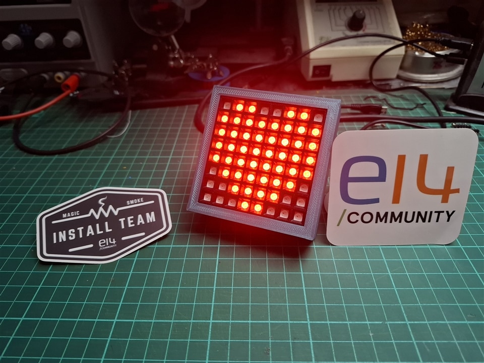
With the proof of concept working on the bench, it was time to think about proper integration in a nice looking “toy”.
Powering the toy
The MAX32666FTHR board features a battery management IC and a 3.3V step down converter to properly power the MCU, while the LED array, on the other hand, requires 5V, which meant using a level shifter for communication, as can be seen on the already published video.
I could have decided to require a USB cable to be always connected as a power source, but this somehow felt wrong with the charger IC available on the board itself.
I thought about using a step-up module to go from the generated 3.3V to the required 5V, but this was quickly dismissed as the current requirement for LEDs is simply too high for the step-up module present on the board.
The decision was then taken to add a dedicated “battery management / +5V@2A charger and step-up” module, based on the FM5324 chipset as found on a well-known Chinese marketplace. In order to still power the MAX32666FTHR board, it was necessary to plug the battery on both boards, which led to some interrogations on my side.
After careful experimentation, it was seen as safe to do so, which also meant that the board would consume power from the battery all the time, severely impacting its lifetime.
I did not consider using sleep mode for the MCU as the LED panel has no such feature and so resorted to the good old “mechanical power switch” on the positive battery lead.
The FM5324 datasheet suggests that the +5V output will be probed regularly for current consumption and will be turned on if there are at least 80mA drawn permanently. Sadly, putting a 47ohms resistor across the output did not turn on the step-up output automatically, so I had to add a switch to the TAPW pin and use it to “force” the +5V output start up.
With a top current consumption of nearly 2A when the display is fully white, I chose to use a 5000mAh battery so that I didn't have to charge the toy too often. A smaller battery would obviously mean a slimmer toy, but I believe there is a nice feeling of having a sturdy object in hand.
Brightness control
The FastLED library offers a way to limit current consumption by the LED array with a simple call to its setBrightness method. With this, the user code writes the same values into the display memory, and FastLED does all the heavy computation to adjust the effective values to match the requested brightness.
My initial testing was done with a constant value that avoided me getting blinded by the light, but I wanted the final product to allow changing the value easily.
The most user-friendly way that I could find was to use a potentiometer configured as a voltage divider, and whose midpoint would be fed to an analog pin on the MCU.
One very strange thing with the ADCs embedded in the MAX32666 is that the maximum voltage they can read is limited to the VREF value, which can either be an internal 1.22V reference or half the VDDA voltage. But finding the real value for the VDDA voltage in the datasheet is really difficult as it’s not clearly stated in the electrical characteristics. In the end, I believe that it’s connected externally to VREGO_A, whose value is set to 1.77V on reset (table 4-21), leading to a 0.885V reference value for the ADC. That value was so small that I decided to use the advertised 1.22 bandgap reference.
The datasheet also says that the ADC configuration must respect equation 10-3:

But it does not say anything about what happens if we don’t respect this. Will it fry the ADC? Will it saturate the ADC and give a 0X3FF value?
To be on the safe side, I configured the ADC to use the 1.22V reference with ref_scale = 0, use scale = 0 to get no postscaling, but also set adc_divsel to 0x2 to apply a division by 3 to the input signal.
The intention was to get 3.3/3 = 1.1V as the maximum input value, just below the 1.22V reference.
Well, once again, things did not work as expected, and I can’t help it but think the datasheet is lying to me. Indeed, the result value from the ADC was 0x3FF at the middle of the run of the potentiometer! This answered the question above, it did not fry the ADC, just saturate it.
The fix as easy, just set scale to 1 and this gives a division by 3 followed by 2 and a finally a full-scale readout out of the ADC.
User control
I could have made a “single use” toy, requiring reprogramming every time a new game mode was thought about, but this felt cumbersome. As I love mechanical switches for their clarity, I decided to add an 8-position rotary switch. Yes, it is bulky but I love the feeling of clicking through its positions.
The way it works is that each position connects a different pin to the two “common” pins on the side, and all are left floating while rotating.
I could have connected those 8 lines to 8 GPIO pins on the MAX32666FTHR board, but this would have meant using half of the available ones and I can’t help but fondly remember the 74LS chip family that I used on projects during my teen years, especially the 74LS148 8 to 3 encoder, halving the pin count requirement.
Obviously, the 74LS family is not suited for this because it requires +5V to work. I could have used another level shifter, but it adds yet another module to an already cramped project.
Luckily, that family evolved since then and there is now the 74HC 148 that accepts power from 2V to 6V, a range where 3.3V fits just fine.
To avoid floating inputs, all 8 lines are pulled up by 10k resistor arrays tied to +3.3V
To be notified of the change of position, we consider the EO output pin which, when transitioning from Low to High indicates a new position has been selected, following this sequence of event:

This is illustrated in this video:
So, I decided to configure a pin on the MAX32666 board as a GPIO input with an interrupt configured on a “RISING” signal.
MSDK gives us a nice-looking example of GPIO interrupt usage, but copying it over sadly does not work, no interrupt gets notified. Hopefully, there was already interrupt-handling done for FastLED so I was able to copy that over.
The only remaining issue is that the interrupt is triggered on both changes despite specifying the appropriate flags in the expected registers. I believe this is a “fast rebound” issue, as can be seen on this oscilloscope trace:
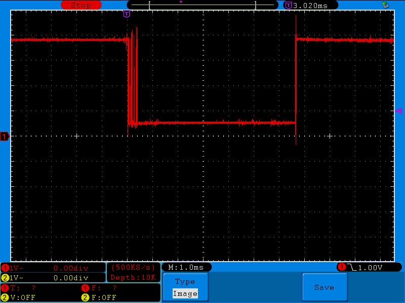
Mechanical switches are known for this kind of behavior, and while RC networks can help, I feel it’s easier to deal with this in software. Indeed, the rotary switch has 4 positions that are unconnected to any of the pins, giving a readout similar to the “rebound” situation, so it’s already a situation that is to be handled.
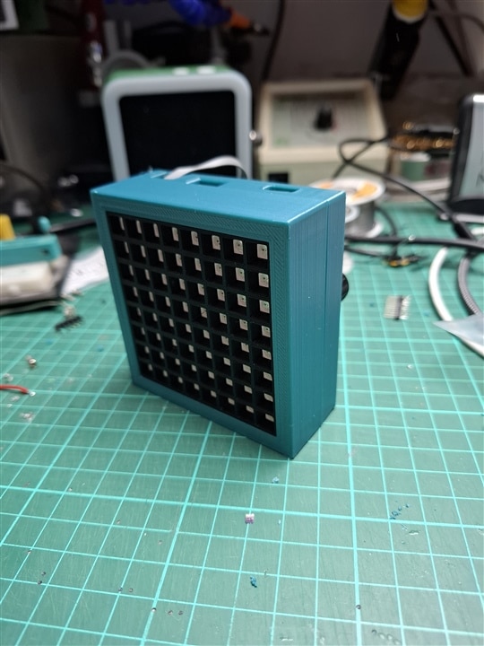
The case
A ready-made case bought “off the shelf” was so unlikely to be found for such a mix of unrelated components that I once again fired up FreeCAD to design my own. This also allows me to see if everything fits beforehand, with the ability to 3D print again a modified version if need be.
To make sure movements are well perceived, I decided to place the BMI160 right in the middle of the case, meaning that the MAX32666FTHR board was off center and very “high” when considered with the display in front of it. And because this is also a development in progress, I wanted most things to still be accessible, which explains the slope to access the SD card, the cutouts for the two USB ports and a hole for the debug connector to fit through.
Here is a video rendition of the various elements and their various positions:
The printed parts are the back, the front, and a reflector that serves two purposes:
- make sure the light from adjacent LEDs do not “pollute” each other
- be an anchor point between the panel and the front case.
After a couple hours print, here are photos taken during assembly:
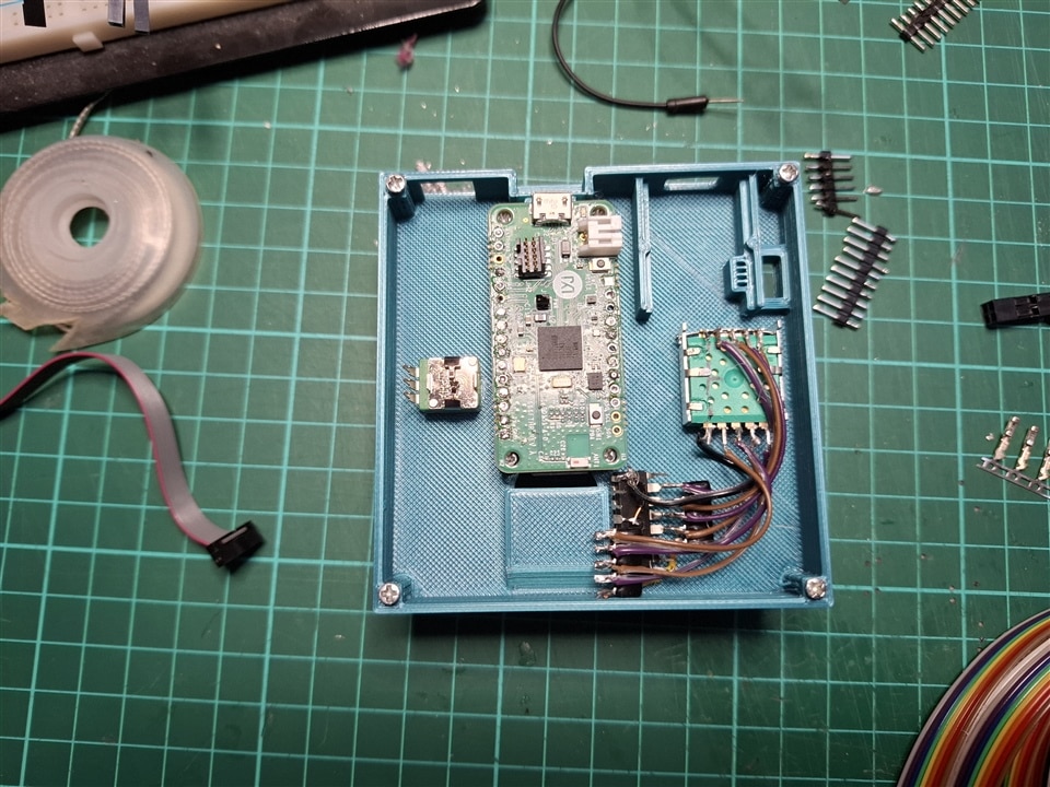
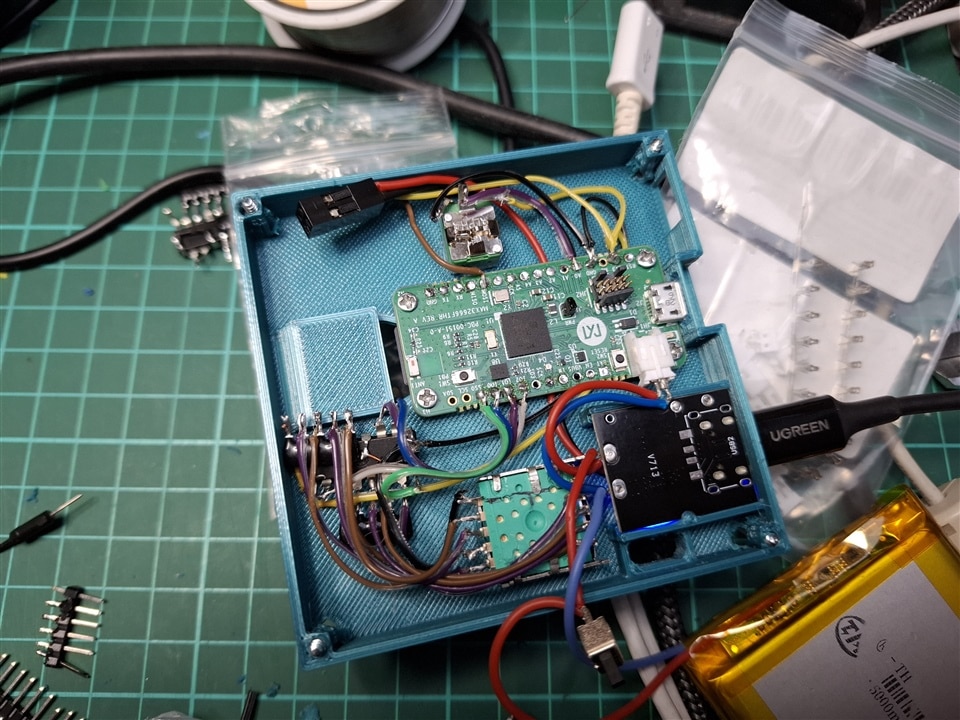
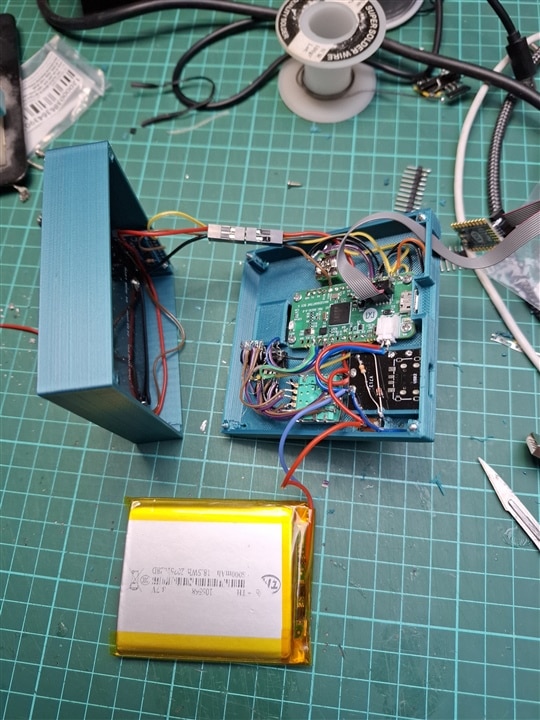
As you can see, there is no PCB for the 74HC148, the pins are bent flat, the resistor arrays are directly soldered to the pins and the connections are done directly with wrapping wire. This may not be the cleanest design, but it meant faster turn time and I also like the "high frequency circuit" feeling it gives to it.
What you don’t see here is that the screws holding everything in place were scavenged over the years on electronic toys or devices that died on me. Some were “self-tapping” but as it turns out, the PLA used for the cases did not like much the procedure, being on the brink of cracking on my first try.
As a result, I decided to self-tap for two or three millimeters, set the soldering iron to 180°C, place its tip inside the middle of the cross imprint on the screw head and apply light pressure until the temperature propagates just enough in the metal to get the PLA to slightly melt. Once the screw is in place, I quickly remove the soldering iron and let everything cool down.
Maybe it would have been better to use the “hot air” end of a soldering station on a low temperature setting to melt the PLA while tapping the screw, but I don’t have such an equipment, so I had to find another method.
Activities
As already said, the toy has multiple modes inside it, that I call activities.
To represent this, the code declares a class per activity, each inheriting from the same base class. This avoids an ugly “switch case” in both the setup and loop functions but allows for a more elegant approach like this:
Activity* activity = ActivityFactory::BuildActivity(activityIndex);
while (1)
    activity->loop();
Obviously, there is a “switch/case” inside the factory, and each class constructor does the required “init” operations, but after that, it’s only a matter of calling the loop virtual function on the activity instance. Should there be other methods to call, they would also be virtual and the main loop would not have to know the exact instance that is being used.
While this is quite elegant, with a good level of abstraction, those of you who are used to performance in constrained environments will already have jumped off their chair saying “One must NOT call virtual methods in a tight loop, the cost is too high”. And indeed, they are right, because for every call to a virtual method, the code has to access the Virtual Method Table (VMT) and find the actual address of the method for the current instance. For a non-virtual method, the linker already knows the address of the target method and direct call can be made, saving precious time.
I already stumbled across this twenty-four years ago when I was writing a control loop for a video capture system to identify remote controlled robots. The solution was to store the result of the VMT lookup in a pointer so that it could be called with a simple jump instruction. Sure, it’s a little bit less efficient than link time static resolution, but the gain was massive in that instance.
Sadly, this only worked because the MSVC compiler has an extension that allows using the & operator on virtual methods, something that the GCC compiler does not allow easily.
But, because this situation has been encountered numerous times before, quite a few people tackled the issue and offered a “fast delegate” solution that basically allows for this VMT result capture to happen. I have tested those:
SRUtil: https://www.codeproject.com/articles/The-Impossibly-Fast-C-Delegates
SA: https://www.codeproject.com/articles/The-Impossibly-Fast-Cplusplus-Delegates-Fixed
Boost: https://www.codeproject.com/articles/Fast-C-Delegate-Boost-Function-drop-in-replacement
FF: https://gist.github.com/vittorioromeo/6462221
The last one was found in the comments section of the third one.
With an empty “loop” function, the difference in call duration is only due to the invocation method and so we should be able to compare those options.
But because the “Boost” one uses the standard Boost library that has not been ported to MSDK, it was immediately ruled out of the competition.
The remaining methods were tested and compared to give this outcome:
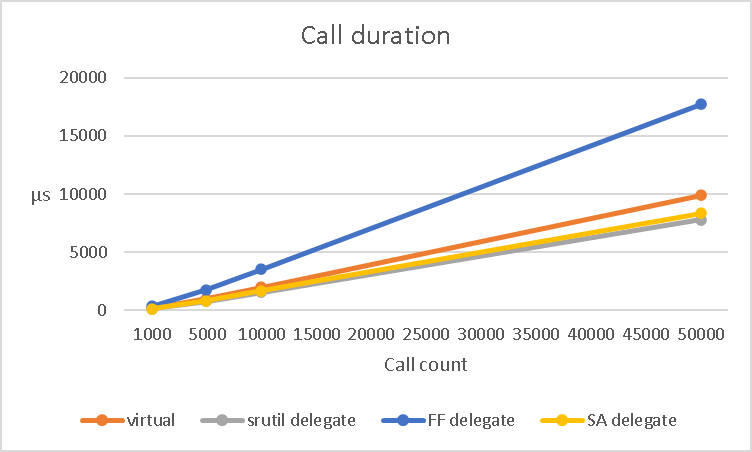
Clearly, FF is not up to the task in our environment, but SA and SRUtil are giving a 15% and 20% average improvement over “virtual” respectively.
With all this figured out, I decided to use the SRUtil delegate and moved on creating the following activities for the toy.
GIF player
This leverages the SD card and FatFS support provided by MSDK.
Changing the currently playing GIF is done by tapping, which is indicated by an interrupt flagged by the BMI160 chip in its registers.
Dice
Shake the toy and you get a number between 1 and 6 displayed, like a regular 6-sided dice. This required me adding the “significant motion” detection support code in the BMI160-Arduino library.
There are various ways to generate a random number, the usual one being to use a Pseudo Random Number Generator (PRNG) like the Mersenne Twister. As the name implies, the number is not really random but it’s usually acceptable for a toy usage.
However, the MAX32666 embeds a True Random Number Generator that I believe uses a “white noise” entropy source to get a truly non-repeatable sequence of bits.
Just for the beauty of it, I thus decided to use the TRNG and I could have read a single 32bits value and find out which 5bit nibble has the highest value, but this leaves 2 bits out, effectively increasing the risk of getting a tie.
So in the end, I read it six 32bit values in a row and use the highest read value index as the dice throw result. The probability of getting a tie is extremely small, but the code caters for it just in case.
The video below also shows dynamic brightness adjustment.
Trace
In this activity, a single pixel is moved around the panel by tilting the toy in all directions, leaving a trace of its passage. The more you tilt, the faster the point moves.
The base idea is once again to use the BMI160 support library and quite notably the getAcceleration method.
However, this initially did not work at all, no values were read despite moving the board around.
The solution came from a thorough search on the internet that lead to this blog post: https://how2electronics.com/interfacing-bmi160-accelerometer-gyroscope-with-arduino/
In particular, this extract from the acceleration code:
  Wire.write(0x7E); // Command register
  Wire.write(0x37); // Start accelerometer offset calibration
In the library that I use, I could find 0x7E as BMI160_RA_CMD but there was no trace of a command value of 0x37. I thus went to the datasheet and it’s not even there!
So clearly, one must execute an undocumented command for acceleration to be read properly, and I have no idea how the person above came to know about it.
USB
The MAX32666 features a USB2 Host Interface with PHY which gave me the idea to create a computer application to control the display via a USB cable.
To do this, the SDK offers two options: MAXUSB and TinyUSB.
I decided to use the latter as it’s targeted at more platform, meaning that learning could prove useful if I encountered the same need with other boards in the future.
Sadly, while the examples are here, and the library ported to MSDK is in the GitHub repository, it’s missing from the regular distribution
It’s not hard to get it from GitHub in the Libraries.tar.xz file or directly by cloning the project, but just for completeness, I created an issue for that.
I started off with the CDC/MSC example as it would, I thought, allow to get both a COM port for communication, and a drive to interact with the SD card on the computer. Sadly, the example does not show how to bring the SDCard to MSC and while someone already asked for such support, it’s not received any answer just yet.
But while the COM port worked just fine in the provided example, my computer failed to properly initialize the USB device once I ported the code into my own project.
After a bit of searching, it all came down to the fact that the interrupt handler was not called, preventing the host interface from properly communicating with the computer.
In the demo, it is declared as such:
//--------------------------------------------------------------------+
// Forward USB interrupt events to TinyUSB IRQ Handler
//--------------------------------------------------------------------+
void USB_IRQHandler(void)
{
    tud_int_handler(0);
}
With apparently nothing more to do, but copy/pasting the exact same code was not working within my project.
And the reason why it failed is coming down to a technicality when compiling a project. To sum up, the compiler creates object files, and the linker puts them all together to create the image file that will be flashed on the chip.
The linker gets function names offered and required by object files and tries to match them all up. If a function is used by an object file but not offered by any other one, you get a linker error.
If two object files are providing the same named function, the linker will also give you an error because there is an ambiguity.
Also, and that’s a feature used by MSDK, one can declare a function as “weak” so that a default implementation is used but can be overwritten by a function with the exact same name in another object file, thus not triggering the ambiguity error.
This is exactly what’s happening with USB_IRQHandler whose provided default implementation is empty and gets replaced by the one in the demo’s .c file.
The only difference from my project is that the demo project uses “.c” files while I use “.cpp” because I’m working with C++ in order to get classes as described above.
And because C++ allows for far more complex method names with classes, namespaces and overloads, the compiler had to find a way to prevent the linker from complaining about ambiguous names when creating the elf image.
This is called name mangling and is explained in great length in gcc source code.
This means that the USB_IRQHandler function declared in my cpp file gets output in the object file under this name: _Z14USB_IRQHandlerv
Quite obviously this is not equal to the one declared in the MSDK object file and so the “automagic” replacement does not occur and the USB stack is broken.
Now, there are two solutions here:
- Tell the C++ compiler to output an unmangled name
To do that, surround the entire method with a extern “C” { … } construct
- Register the interrupt handler manually
Add a line with a call to MXC_NVIC_SetVector(USB_IRQn, USB_IRQHandler);
I chose the second option because I like clarity more than “automagic” linker behavior.
With this sorted, I still needed to define a communication protocol between the toy and the controlling app. As I already did this in my openHAB weather station, I once more used the FlatBuffers library and defined a simple message that caries the entire LED array status.
For the application, because I am also hoping to get Bluetooth communication working, I used a development environment that can target both Windows and Android with the same source code and a visual approach, namely Embarcadero RAD Studio. Yes, I know, it’s a bit exotic and some of you may even say that “Delphi is dead” but as I’m using it on a daily basis for professional work, I felt right at home here.
And here is the end result:
Conclusion
Initially, I just wanted to display an animation on a LED matrix that had been lying around far too long.
But choosing to use the MAX32666FTHR board instead of a more common ESP32Dev one changed the entire project from a laid down journey to more of a roadtest report.
I’m actually glad I took the time to go through all those hurdles because I learnt or refreshed memory on quite a few things along the way, from precise timing conditions to linker magic behavior.
This also meant that what I initially had in mind with an embedded Javascript engine and an app running on my Android phone to control the board and transfer files had to be ditched for me to respect the deadline. Same goes for the aspect of the case that could have gotten a smoother finish had I had the opportunity to investigate using a hot air source to slightly melt the surface.
But I’ll keep working on this and will make sure that I report back here when there is progress on that front, hopefully in the coming weeks/months.
Code for the toy itself and its app are available online here:
https://github.com/obones/max32666toy
https://github.com/obones/max32666toy_app
I hope you enjoyed reading about this as much as I enjoyed creating this toy, and as usual, do not hesitate to ask me for clarifications or additional information.


