 | Enter Your Electronics & Design Project for a chance to win a $100 Shopping Cart! | Project14 Home |
| Monthly Themes | ||
| Monthly Theme Poll |
Previous post in this blog sequence:
Kitchen Lighting System Phase 2
Kitchen Lighting System Phase 2 - Part 2
Kitchen Lighting System Phase 2 - part 3 - Let there be (better) light!
Kitchen Lighting System Phase 2 - PCBs, Schematics and new sensor module.
Kitchen Lighting System Phase 2 - PCBs have arrived!
The deadline of this Project14 competition is rapidly approaching and I am up to my neck and nearly drowning in things to be done, like getting the EnOcean radio links integrated into the project. First it was a hardware problem. When I was assembling the 'Master/PIR' pcbs, I noticed that the bottoms of radio modules (TCM310U) appeared to be in with some of my vias on the PCB (I guess I did not think that the TCM310U's PCB would have been flush with my PCB after soldering, wrong!). I started measuring resistances on the various pins of the TCM310U with my power and grounds and oops, there were some unintended connections. So I started over on a new board, this time isolating the vias in my PCB with tape and soldering on the TCM310U. When measuring resistances on the pins, I still saw some unintended connections. Looking further the problem got a little clearer. It appears that I had made an error while creating the library element of the TCM310U in eagle. I had the pin connections skewed a bit, where several of the pins were one pin off. Bummer! I re-worked the boards and re-order PCBs for the Master/PIR and standalone radio PCB. Later, I decided to cut and jumper the remaining Master/PIR PCB to see if I could get a module working so I could start working on the firmware.
The PCBs were not my only delays. Due to poor timing, I am not getting much time to work on this project. My primary commitments over the past two weeks have been entertaining my Mother, who was visiting us and handling site prep work for getting my shop built. Over the past two weeks I have cut and cleared about 15 trees in the adjacent lot (with the owners approval), in order to make a clear path to bring in a cement truck to pour my foundation. This took several days, broken up by some rainy weather. I have finally worked my way through the majority of these issues, but only have a few days left in this competition. I will do the best I can, but feel that I will not complete in time.
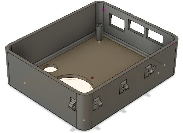
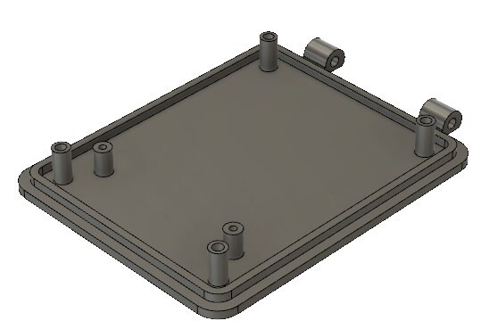
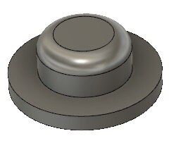
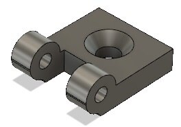
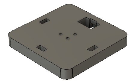
Since the prior post, I have been working to design the enclosure for the Master/PIR module. This module will mount under the overhead cabinets and provide a PIR view of the walking space in the kitchen to turn on the lighting. There will be two modules, mounted on either side of the kitchen, at the two opposite corners, looking towards the center of the kitchen. To properly view the interior of the kitchen, the modules need to slightly tip to peek out from under the cabinets. The case is made up of several parts, each shown below:
The printed parts are shown below:
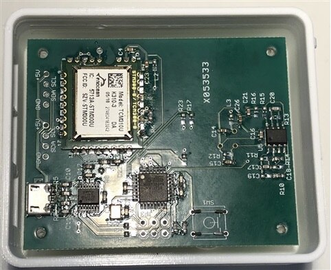
The PCB shown in this series is the first reject. I had most of the board assembled when I decided to start checking the TCM310U modules connections. I was installing components on the back side of the PCB when I noticed some the TCM310 traces and vias present through the vias on my PCB. This tipped me off that I might have a problem, so I started probing. The Master/PID is corner mounted and tilted, hence the pivots and slanted standoffs attached to the back of the case for mounting.
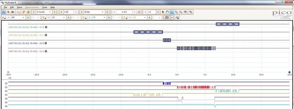
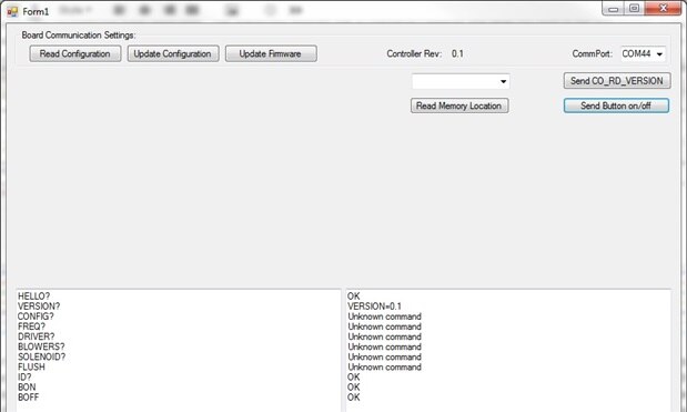
One of the largest unknowns in this project for me has been the EnOcean transceiver. While I have used these parts in the past, I did so, only as receivers. The whole concept of transmitting the telegraphs was new to me. After a couple of days of work, I have worked through the details of sending and receiving EnOcean telegraphs. The Master/PIR modules has a USB/serial converter that while not used in the final product, it also me to send commands and receive replies between a control panel (PC-base, Visual Studio 2008) and the connected Master/PIR module. I use this to send a request to the Master/PIR module, which in turns builds and sends a command to the TCM310U and waits and decodes the replay, which is sent back out to the control panel. Here is a sample of the communications:
The top four traces are the serial decoding of the USB/serial (9600 baud) link and the serial lines to/from the TCM310U (58.8K baud). Below are the actual serial traces (blue/red/green/yellow) ans some debug traces showing the EnOcean receive routine state machine values. In this example, the PC sends out a message ("ID?\r\n"), which is followed by the microcontroller sending out a CO_RD_VERSION command to query the TCM310's APP and API versions as well as the chip ID, Version and App description. In response to the query the TCM310U sends a reply which is decoded and then the microcontroller replies ("OK\r\n") to show the return value on the control panel. The final three traces are showing the various states (inverted all high = 0, all low = 7) during the receipt and decode of the TCM310U's reply the state = 0, indicate idle, then state = 1 as the SYNC byte is seen, and the header is being read, state= 2 as the header CRC is checked, then state = 3 as the data values are read, and then state = 4 as the data CRC is checked, and then state = 0 a return to the idle state. So far, so good, to bad it took a couple of days of writing code and hunting bugs to get to this point.
The next step was to get the TCM310U to actually transmit a message. To do this, I added a button to send out a pair of EnOcean messages (BON - button press and BOFF - button release). There is a delay between the two messages, and the scope capture below shows the 'press' message sequence:
The top four traces are the serial decoding of the USB/serial (9600 baud) link and the serial lines to/from the TCM310U (58.8K baud). Below are the actual serial traces (blue/red/green/yellow) ans some debug traces showing the EnOcean receive routine state machine values. In this example, the PC sends out a message ("BON\r\n"), which is followed by the microcontroller sending out a button pressed message (Radio message 0xF6 with 0x10 data, along with device ID, etc. ). In response to the message the TCM310U sends a reply which is decoded and then the microcontroller replies ("OK\r\n") to show the return value on the control panel. The final three traces are showing the various states (inverted all high = 0, all low = 7) during the receipt and decode of the TCM310U's reply the state = 0, indicate idle, then state = 1 as the SYNC byte is seen, and the header is being read, state= 2 as the header CRC is checked, then state = 3 as the data values are read, and then state = 4 as the data CRC is checked, and then state = 0 a return to the idle state. The EnOcean message was captured using DolphinView with an attached USB/Gateway and is shown below:
The pair of messages where receives RPS with data 10 (press) and RPS with data 00 (release). The IDs of both messages match the ID of the TCM310U attached to the Master/PIR pcb.
From here, I need to code a whole bunch more functionality into the Master/PIR firmware to handle the embedded PIR sensor and RTC module, plus two master I2C modules (connected light pucks and RTC). I also need to build up the remote light switch that mounts in the microwave. So I better get back to work!
Thanks for reading along.
Gene







Top Comments
-

fmilburn
-
Cancel
-
Vote Up
+1
Vote Down
-
-
Sign in to reply
-
More
-
Cancel
Comment-

fmilburn
-
Cancel
-
Vote Up
+1
Vote Down
-
-
Sign in to reply
-
More
-
Cancel
Children