 | Enter Your Project for a chance to win an Arduino MKR WAN 1300 Kit with a Compatable Lora Gateway or an MKR 1400 GSM with a Shield Combo + a $100 shopping cart! | Project14 Home |
| Monthly Themes | ||
| Monthly Theme Poll |
My project for Arduino Day 2019 is an autonomous sensor device that reports data from a (randomly chosen) sensor and how long it's expected to run before you need to recharge its battery. The focus is not on the sensor (although I'll try to make that meaningful too) I want to build a base that can be used for other designs in the Cloud that need battery monitoring.
I want to have this device reporting how long it's expected to continue living without charging, and raise alarm at near death. I will be using a 3.7 V LiPo battery with a charge / recharge manager to monitor the battery health. That will tell me how much power budget I have. And I want to specify my design's power profile to predict how much energy it will use in the future. With that data I can predict how long it will run by itself.
An additional goal is to make the design low-power. |
Ingredients:
- WiFi
- Secure MQTT with Certificate based authentication
- Amazon Web Sevices (AWS)
- Low Power
- Battery Management - external charge circuit with fuel gauge
Step 1: Low Power operation
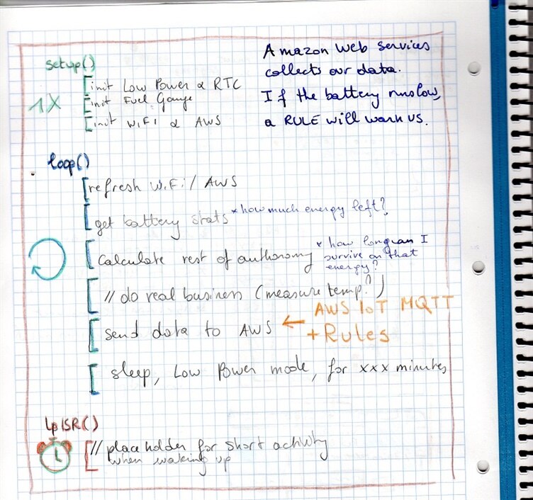
My design is going to sleep most of the time.
At predefined wake-up intervals, it'll do its business (a sensor query and battery check).
It will post data to an Amazon Web Service, where that info can be collected and acted upon.
Because I want to start the design with low power use as a basis, I decided to investigate that first.
Arduino has published a Low Power Library for SAMD21 based boards. I'm using it's TimedWakeup sketch as the core for my program.
This example puts the device to sleep for a given period. At each wakeup, it calls an interrupt handler, then runs one loop().
That's a decent start for my low power device.
Library dependencies:
- RTCZero: real time clock library for Arduino Zero. Also works on this MKR 1010.
- Arduino Low Power: Functions to make the MKR WIFI 1010 go to sleep. I use the RTC to make it wake up at given intervals.
Most of the time, the biggest consumer is that the green ON LED was is always lit.
That consumes 7.7 mA. That's why it's marked NO on the pcb  .
.
I removed it from the Arduino.
image: the ON LED desoldered from the pcb.
TimedWakeup
That's the name of the sketch from the Low Power lib that I use as starting point.
At the end of each loop(), it tells the Arduino to go sleep for a while.
You can choose the sleep mode: sleep or deep sleep, by defining DEEP_SLEEP as 0 or 1.
At wakeup, it first calls an interrupt service routine.
You can perform some quick things there, like setting flags. Don't put slow code in the ISR.
Then, it lets the loop() execute another cycle and goes back to sleep.
Repeat forever.
Because it's hard to re-program a device that's in sleep mode most of the time (the USB port is inactive during sleep), I made a construct to keep it awake when needed. When you drive D0 high, the firmware will not call the next sleep mode and you can happily reprogram the Arduino. |
#include "ArduinoLowPower.h"

#define SLEEP_MILLIS 900000U
#define DEEP_SLEEP 1
#define PIN_KEEPAWAKE 0

void setup() {
  pinMode(PIN_KEEPAWAKE, INPUT_PULLDOWN);
  LowPower.attachInterruptWakeup(RTC_ALARM_WAKEUP, lpISR, CHANGE);
}

void loop() {
  // Triggers a 2000 ms sleep (the device will be woken up only by the registered wakeup sources and by internal RTC)
  // The power consumption of the chip will drop consistently
  if (!digitalRead(PIN_KEEPAWAKE)) { // skip sleep if D0 is driven high.
#if DEEP_SLEEP == 1
    LowPower.deepSleep((uint32_t)(SLEEP_MILLIS));
#else
    LowPower.sleep((uint32_t)(SLEEP_MILLIS));
#endif
  }
}

void lpISR() {
  // This function will be called once on device wakeup
  // You can do some little operations here (like changing variables which will be used in the loop)
  // Remember to avoid calling delay() and long running functions since this functions executes in interrupt context
}
Step 2: Hardware
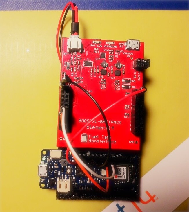
image: connections between the battery pack and the MKR WIFI 1010
Why an External Battery Manager?
The MKR WIFI 1010 has a battery manager on board. But that one can't report battery health.
I'm using a battery charger with embedded fuel gauge (the element14 /TI Battery BoosterPack - modded for efficiency).
That one has a bq27510-G3bq27510-G3 Li-ion battery fuel gauge on board that maintains stats on the battery capacity.
I can ask it how many Ah remain in the battery, an indication for how long it can survive before charging is needed.
image: fuel gauge and battery charger from the BoosterPack. Source: BOOSTXL-BATTPACK User's Guide
i2c Bus
There's a decent amount of devices connected to the i2c bus:
- WiFI module
- Battery Charger (that I don't use)
- CryptoAuthentication Device
- External fuel gauge IC
The Arduino has 4k7 pull-ups on board. I disabled the ones on the battery management module.
Step 3: Collect Battery Statistics
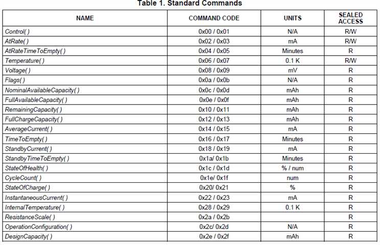
image: fuel gauge standard commands available via i2c. Source: bq27510-G3 datasheet
Battery Statistics Sketch
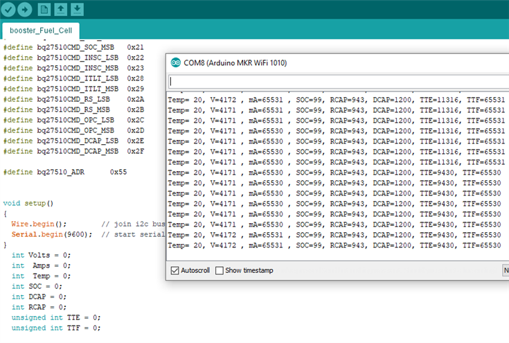
Our very own Robert Peter Oakes wrote a sketch to read the statistics from the fuel gauge.
It worked straight way on the MKR WIFI 1010.
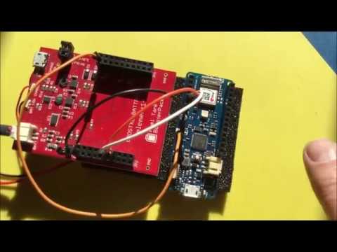
image: the MKR WIFI 1010 runs Peter Oakes' sketch to get data from the Fuel Tank BoosterPack
Definition of the not-so-common stats:
TTE: Time-to-empty
TTF: Time-to-full
SOC: State-of-charge in percent related to FCC
FCC: Full charge capacity. Total capacity of the battery compensated for present load current, temperature, and aging effects (reduction in chemical capacity and increase in internal impedance).
DCAP: Design Capacity
RCAP: Remaining Capacity
FRM:filtered compensated battery capacity remaining
Calculate Remaining Authonomy
There's a rule of thumb approach on the Arduino website: https://www.arduino.cc/en/Tutorial/MKR1000BatteryLife
The formule they use is:
Battery Life = (Battery Capacity) / (Average Current Consumption) * 0.7
When the battery is 70 %discharged, they advise you to charge it again, to avoid deep discharge and deal with variations (like temperature).
I'm taking over the 70% rule.
However, because I have a good estimate of remaining capacity from the fuel gauge, I will not take in account the on-time and average current consumption to calculate the battery statistics.
I will use the average current consumption to extrapolate remaining on-time though.
Measuring that average current is done in a different blog post. I will use the results here once that's finished.
Step 4: Set up the Amazone Web Service
Secure Connection
Setting up a secure connection with AWS is a topic on its own. Arduino has provided an excellent how-to that brings you from "Zero" to "MQTT Working".
I dedicated a separate blog post on that topic.
Use the Data and AWS Rules
In this blog post I'm focusing on getting the data safely to the AWS MQTT server.
I'm writing another post on how to move it from the MQTT server to a database, how to report on it, and how to set up a rule if the battery capacity drops below 70%.
It is a topic that is fully independent from the device design, so a separate post will be less clutter. And I still have to learn it  .
.
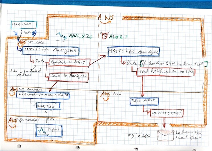
(edit: I learned it now. Here is the flow between the AWS services, for data capture, analysis and alerting)
Manage Arduino MKR WIFI 1010 Battery Life in the Cloud - AWS, Graphs and Alerts
Step 5: Send Structured MQTT Messages
JSON
To make it easier to parse data on the AWS side, I want to structure the payload.
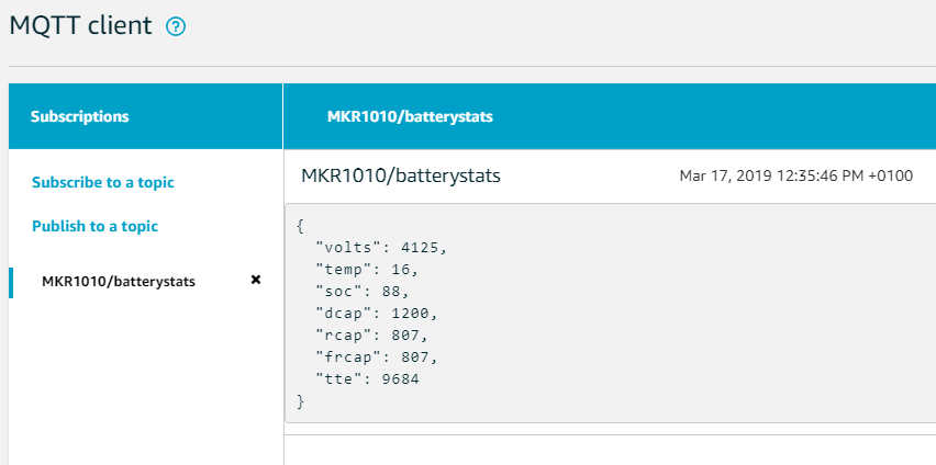
I'm formatting the info into a JSON structure. That structure holds data name and value, and can be extracted without manual parsing later.
I'm conservative here, and use printf to construct the data. The better me would create a class that has members for all data points and a method to stream itself to a JSON string.
Maybe later...
void publishMessage() {
#if DEBUG_TO_SERIAL == 1
  Serial.println("Publishing message");
#endif

  char output[80];
  // send message, the Print interface can be used to set the message contents
  mqttClient.beginMessage("MKR1010/batterystats");
  mqttClient.print("{ "); // JSON START

  sprintf(output, "\"volts\": %d", Volts);
  mqttClient.print(output);

  sprintf(output, ", \"temp\": %d", Temp);
  mqttClient.print(output);

  sprintf(output, ", \"soc\": %d", SOC);
  mqttClient.print(output);

  sprintf(output, ", \"dcap\": %d", DCAP);
  mqttClient.print(output);

  sprintf(output, ", \"rcap\": %d", RCAP);
  mqttClient.print(output);

  sprintf(output, ", \"frcap\": %d", FRCAP);
  mqttClient.print(output);

  sprintf(output, ", \"tte\": %d", TTE);
  mqttClient.print(output);

  mqttClient.print(" }"); // JSON END
  mqttClient.endMessage();
}
In the AWS testbed, you can see the message arriving:
The sketch is attached.





Top Comments
-

Jan Cumps
-
Cancel
-
Vote Up
+3
Vote Down
-
-
Sign in to reply
-
More
-
Cancel
-

Jan Cumps
in reply to Jan Cumps
-
Cancel
-
Vote Up
+4
Vote Down
-
-
Sign in to reply
-
More
-
Cancel
Comment-

Jan Cumps
in reply to Jan Cumps
-
Cancel
-
Vote Up
+4
Vote Down
-
-
Sign in to reply
-
More
-
Cancel
Children