


Hello everyone.
In this blog post I would like to describe my second project for a NFC or RFID Project14 Competition. In this project I utilized my own dynamic tag. This project tis about thermometer with output readable via NFC. Idea is that thermometer reads temperature at the background and saves output to the NFC tag. When you touch phone (or other NFC reader) to the tag, you can read the latest measured temperature.
Sample Sponsors
Experiments was also sponsored by ST. ST send me free samples of ST25DV64KC-IE6T3 NFC Tags. I ordered them in the time when shipping on their store was free, so I received them totally for free.

See it in the action!
On following video, you can see my final build in the action. Before recording I opened window. For this reason, ambient temperature decreased to about 16 °C. Then I touched thermometer by finger which increased temperature and after thermometer recorded new temperate (short green LED blink) I read new temperature with my phone again. Phone application is standard NFC reader app. It is designed for use without need to use project specific application.
Components
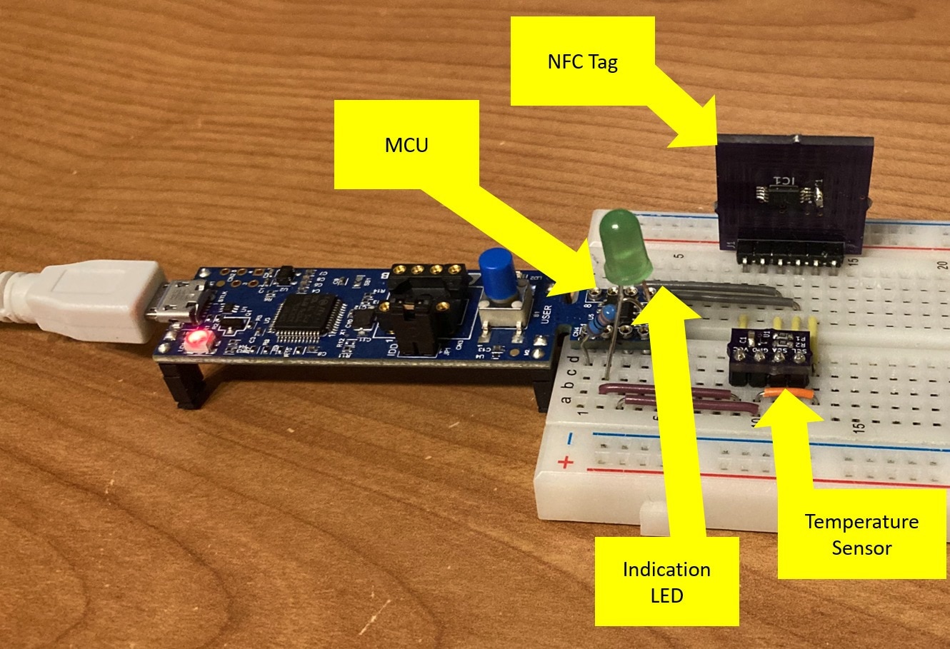
Devices integrates 4 components:
- STMicroelectronics STM32G031 microcontroller in SO8 package.
- Maxim Integrated (ADI) MAX31875 I2C Temperature Sensor on my own breakout board.
- STMicroelectronics ST25DV64KC-IE6T3 Dynamic I2C NFC Type-5 Tag
- Green LED

BOM
Bill of Materials
| Product Name | Manufacturer | Quantity | Buy Kit |
|---|---|---|---|
| STM32G0316-DISCO, Discovery Kit, STM32G031J6M6U, 32 Bit, ARM Cortex-M0+ | STMICROELECTRONICS | 1 | Buy Now |
| ST25DV64KC-IE8T3, NFC Tag | STMICROELECTRONICS | 1 | Buy Now |
| MAX31875R0TZS+T, Temperature Sensor, ± 1°C, -20 °C, 150 °C, WLP4 | MAXIM INTEGRATED / ANALOG DEVICES | 1 | Buy Now |
| CRG0603F4K7, SMD, 4.7 kohm, ± 1%, 100 mW, 0603, Thick Film | NEOHM - TE CONNECTIVITY | 5 | Buy Now |
| C1608X7R1E104K080AA, SMD MLCC, 0.1 µF, 25 V, 0603, ± 10%, X7R | TDK | 2 | Buy Now |
| TSW-106-08-L-S-RA, Pin Header, 2.54 mm, 1 Rows, 6 Contacts, THT, Right Angle | SAMTEC | 1 | Buy Now |
| CC0603JRNPO9BN560, SMD MLCC, 56 pF, 50 V, 0603, ± 5%, C0G / NP0 | YAGEO | 1 | Buy Now |
| MC0603N100J500CT, SMD MLCC, 10 pF, 50 V, 0603, ± 5%, C0G / NP0 | MULTICOMP PRO | 3 | Buy Now |
| 885012206078, SMD MLCC, 150 pF, 50 V, 0603, ± 10%, X7R | WURTH ELEKTRONIK | 1 | Buy Now |
| MCL053GD, LED, Green, THT, T-1 3/4 (5mm), 20 mA, 2.1 V, 570 nm | MULTICOMP PRO | 1 | Buy Now |
| MCF 0.25W 330R, THT, 330 ohm, 250 mW, ± 5%, 250 V | MULTICOMP PRO | 1 | Buy Now |
| MC001795, Breadboard, 830 Tie Points | MULTICOMP | 1 | Buy Now |
| MC001810, Jumper Wire Kit, Multicolour, 2 mm - 125 mm, 22 AWG, 140 Piece | MULTICOMP | 1 | Buy Now |
Additional Parts
| Product Name | Manufacturer | Quantity |
|---|---|---|
| NFC Tag PCB | OSHPark | 1 |
| MAX31875 Breakout PCB | OSHPark | 1 |
Schematics
Schematics is very similar to block diagram. Interconnects are very simple. There are only 3 MCU GPIOs connected. Two for I2C (SDA and SCL) and third for LED. Other pins are used for reset and SWD, but they are not important for the project. At the end of this blog you can download this schematics in PDF format.

On breadboard it looks as follows:
Custom NFC Tags
In this project I used my self-designed NFC tags. I designed more types of tags. If you are more interested in my tags, you fan find more detailed description in my second project Custom NFC Tags which I did as part of this Project14 contest.
Firmware
Firmware is developed using STM32CubeIDE and it is written in C. I used STM32CubeMX configurator for generating drivers for I2C, GPIO and RTC controllers (I will describe reasons for RTC later). For interfacing MAX31875 temperature sensor it utilizes my own Open-Source library which I published on Github. As part of this project, I ported it to the STM32 platform. For writing NFC tag, I wrote very simple function which can write first 255 bytes of user memory area of the tag. This is sufficient for this project. It is implemented in DynamicTag.c file. Application logic is implemented in ThermometerApp.c file. It integrates error handling and error correction. Application can “survive” errors from both sensor and NFC tag and try to reinitialize it after error occur. Application also checks for CRC errors from temperature sensor (and also properly generates CRC when configuring sensor). You should never face invalid temperature reading. CRC is good capability of MAX31875 temperature sensor.
Tag Memory Lifespan
Application read temperature every 4 seconds, but NFC tag memory lifespan is not infinite. It is about 1 000 000 writes (depends on temperature, million is at 25 °C). When writing new temperature to the tag every 4 seconds it lifespan is limited to about 46 days. For this reason application do it differently. It remember last temperature written to the tag and saves new temperature to the tag only if it changed from previously saved value by at least 0.3 °C and at least 20 seconds (5 measuring cycles) elapsed since previous write. This mean that if temperature do not change rapidly (which is common behaviour of ambient temperature) tag is write-stressed only rarely. Three times per hour or something like this.
Low-Power Operation
I designed application as low power. It incorporates only 3 chips and I deployed the deepest possible stop mode in MCU firmware (there are also modes when MCU memory is not retained, but I did not go sleep so deep). For waking up I use RTC peripheral which is configured to wake up MCU after 4 second elapsed since going sleep.
Because I recently received Nordic Power Profiler Kit, I used it for analysis. I connected PPK 2 to the STM32G031 DISCO:

Then I start collecting power consumption traces. Following screenshot from the profiler shows power consumption of the device.

On screenshot you can see spikes which occurs every 4 seconds. This make sense because sensor every 4 second wake up and collect temperature measurement form the temperature sensor. You can see that many spikes are very similar but there are 4 (5 if you count the latest spike on the right edge) which are higher. In case of these spikes, device not only collected temperature but also evaluated that it is needed to update output in NFC tag and blink by LED for 50ms. Following screenshot shows spike that occurred when device was issuing I2C transaction to the temperature sensor (and both devices were executing their logic). It is about 3.5 mA spike every 4 seconds. We can also see detail of power consumption which looked like noise on previous screenshot. They are some smaller spikes, but they are irregular. Some of them are missing and frequency is not very fixed. Now I know their source and I will show it later.

Following screenshot show detail of larger peak which contains NFC write and LED blink operation. It is easy to understand all parts of this operation. Power consumption is most of the time below 5 mA but it is increased to this level for significantly higher amount of time in comparison with spikes which do not result to NFC write.

As far average (long-term) power consumption of the device is about 85 uA (0.085 mA). This power consumption is good for battery powered device but still can be much better. It is caused mostly by frequent small spikes which was visible on second image (and on first image they were visible as noise). There are three candidates for their source:
- MCU and especially its LSI oscillator and RTC peripheral which are the only peripherals running.
- Temperature Sensor and its internal engine/timer for scheduling regular measurements.
- NFC Tag which is black box. “Nobody” knows what is inside.
I tried to disconnect temperature sensor and spikes did not disappear, so temperature sensor is not their cause. Before disconnecting MCU (which virtually disconnect everything) I tried to disconnect NFC tag and noise disappear. After reconnecting it appears again.

So now I know source of the most power consumption of the device. Next, I checked datasheet how to minimize power consumption of the NFC Tag chip and found reference to Low power down mode. According to the datasheet it reduces power consumption to less than 1 uA. Note that spikes are
about 400 uA. But unluckily this feature is available only on packages with more pins.  It is good point to choose right package when choosing dynamic tags for low-power application.

But for me this was sufficient outcome from the project. Now I know that power consumption of the MCU and temperature sensor is very low (when sleeping) and NFC tag requires more polishing than I originally expected but it is still good result, I think.
Conclusion
This is all form my project presentation. Thank you for reading this blog post. In this blog post you have seen my project with my custom dynamic NFC tags used for making user interface to the low-power application without and display or connectivity. It was cool project for me because I was using dynamic tags for a first time. I had also opportunity to measure (and analyse) power consumption by Nordic Profiler Kit. If you are interested in making this project yourself, feel free to download attachments below. BOM table with links to components is above in the BOM section.
Resources
- Schematics (PDF)
- MAX31875 Breakout Schematics (PDF)
- MAX31875 Breakout Gerbers (ZIP)
- MAX31875 Breakout Kicad Project (ZIP)
- MAX31875 Library (Github)
- ST25DV64KC Dynamic NFC Tag Schematics (PDF)
- ST25DV64KC Dynamic NFC Tag Gerbers (ZIP)
- ST25DV64KC Dynamic NFC Tag Kicad Project (ZIP)
- STM32G031 Firmware Sources Project (ZIP)
- STM32G031 Firmware binary (ELF)
Top Comments