

 Connectors Series - Part 8 - FPGA
Technological advancements have enabled more functionality and intelligence in today's electronic systems than ever thought possible. The relentless demand for higher performance and faster data rates from data centers, IoT systems, 5G, HPC, and other applications has raised needs that FPGAs are uniquely suited to address. System architects and FPGA hardware designers are challenged to balance increasing throughput and scalability needs with low power consumption, signal integrity, cost, time-to-market, and other concerns. As the performance of FPGAs increases, board connection strategies and interconnect designs must likewise evolve.
Connectors and cable interconnects form critical elements of a complete FPGA design solution. They carry digital signals from one device to another, either routed among PCBs or connected to external devices. Common-mode noise, crosstalk, resonances, losses due to signal-path impedances, and other effects can impact signal integrity at high (Gbps) speeds. Hardware designers of high-speed FPGA systems must use best practices to ensure proper signal integrity with high-speed board-to-board, cable-to-board, backplane, or cable-to-cable interconnect. This learning module discusses high-performance interconnect solutions that simplify interfacing to FPGAs and exceed the performance demands of next-generation FPGA-based applications.
Related Components | Test Your Knowledge 
Summer of FPGA | FPGA Group | Samtec Agenda | Tech Spotlight 1 | Tech Spotlight 2 | Related Webinar
sponsored by
2. Objectives
Upon completion of this module, you will be able to:
- Describe high-performance interconnect solutions for FPGAs
- Explain the features and requirements of interconnects
- Define types of connectors and cables relevant for FPGA interfacing
- Discuss application-specific interconnects and solutions for FPGA Boards
3. Basic Concepts
The latest FPGAs incorporate high data transfer rates exceeding 100 Gbps and more. The flexibility, parallelism, and reconfigurability of FPGAs make them an ideal solution for systems that demand a diverse set of high-speed I/O requirements. Along with the high-speed I/O capabilities, FPGAs provide millions of configurable gates, lots of on-chip static memory, and additional dedicated system resources such as processor cores, phase-locked loops (PLLs), digital signal processing (DSP) blocks, PCI Express (PCIe) channels, and memory controllers. External data movement is limited by how fast and how far data can move through the cable assemblies and other interconnects that tie all the switches, routers, and storage arrays together.
Interconnects remain an essential part of high-performance system design, enabling the transfer of signals at the device, board, module, and enclosure levels. In high-performance systems, every element must be optimized for the entire system to meet performance, schedule constraints, size, and cost. Every link in the chain must be robust enough for the entire system to meet the demanding performance specs of today's high-speed products. Interconnects affect system performance adversely if they are not chosen correctly. Passive components, such as connectors, are accountable for increasing design cost, complexity, and footprint. A connector can add substantial EMI emissions, crosstalk, and parasitic capacitance to a circuit, and thus needs special consideration.
- 3.1 Connector Basics
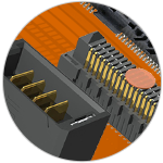
Connector design is a complicated, multi-disciplinary endeavor. While connectors lack the nanometer process dimensions of integrated circuits, their contacts are mechanical structures with tiny elements, tight tolerances, and ultra-thin precious and nonprecious metal plating. Their bodies are incredibly precise moldings. Mechanical, manufacturing, and Signal Integrity (SI) engineers collaborate in designing connectors relevant for boards and applications. SI engineers are responsible for impedance, crosstalk, and insertion loss; mechanical engineers are mindful of stack-up tolerances, normal force, or mating cycles, and manufacturing engineers consider the tooling or molding of connectors. Figure 1 represents a snippet of a wide range of Samtec connectors available in the market.
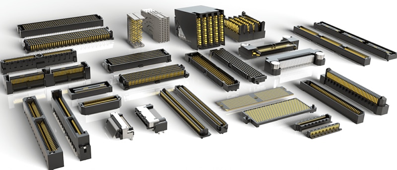
Figure 1: A wide range of connectors
- 3.2 Connector Selection for FPGA Applications
The primary consideration during high-performance connector system selection is the quality level needed for your application. For example, in the case of high-performance interconnects for FPGA applications (e.g., for data centers, IoT, 5G, and HPC), quality cannot be compromised. It is best to limit the scope to determine the connector type required, whether it is PCB, board-to-board, cable assembly, and so on. The sheer number of options can make it a challenge to find a suitable connector set. Parsing down the connector into bite-sized pieces helps identify which traits we need and what we should keep in focus. The following are the most common traits to find a mated set that fits your application's needs:
- Pitch (2.54 mm, 100", 2.00 mm, 1.00 mm, etc.)
- Mate type (socket or pin, stack height if connecting two boards, etc.)
- Open pin field design (provides flexibility of unassigned, yet customizable, pins on a connector)
- Connector use (for example, power, data, or RF)
- EMI/EMC requirements
- Plating type (tin or gold)
- Operating environment (high vibration, high mating cycles, etc.)
- Retention force (how easy it is to remove the connector from the socket)
- Mating orientation (for example, right-angle, straight, shrouded/pin only, etc.)
- Solder type (surface mount or through-hole)
- Max data rate support
- Power specifications (max current, max voltage, etc.)
Connector Type
Connector type, pitch, mating type, and orientation are easily defined. Mating types must match the application, like board-to-board, cable-to-board, or interface-specific. For the pitch of a connector, it is typical to match the current board pitch, and for ease of processing, most designers specify the biggest pitch their board space allows. A high-speed or RF connector will have different requirements than a power connector, so choosing the correct connector type for the job is the first step.
Manufacturing Specifics
PCB board technology should define manufacturing considerations. If surface mount technology (SMT) is to be used, there are a few questions to consider: How will the part be placed? Does the connector have pick-and-place machine mounts? Does it come on tape and reel? For through-hole technology, we should consider which process will be used, e.g., wave solder or paste-in-hole (also called pin-in-hole and pin-in-paste).
Connector Construction
The connector plating specification must match its use. Although not always the case, one can assume a high-cycle connector must have an extremely thick plating, because many insertions equal many wipes of the contacts. In this particular case, gradual oxidation may be a non-issue. However, using the same connector inside a product where it gets plugged in once and never re-inserted may cause problems. If used in harsh operating environments (with high temperature or vibration), the choice of materials and connection methods are another thing to consider.
Connector Mating
Any connector is only as good as the connector to which it will mate. Contact metals must be of a similar type for mating. A mix of tin and gold is not ideal, since unwanted reactions such as oxidation may occur. The rule of thumb is like-with-like: tin with tin and gold with gold. Another consideration is connector height, which allows designers to ensure that two aligned, parallel boards mate and fit within the enclosure. For this reason, identical connector types are available with the same position count, length, and width, but with one key difference: their heights. By mixing different heights, it is possible to support a wide range of inter-board spacing, called stack height.
Electromagnetic Compatibility
Critical parameters for connectors are their ability to maintain performance and signal integrity within the desired data rates, often in Gbps. Additionally, connectors must maintain a device's electromagnetic compatibility (EMC), a measure of how much the device is affected by EMI as well as how much EMI the device emits. Application-specific EMI or EMC requirements may require shielded interconnects. Using shielding within interconnects can reduce emissions and component count from the design, with reduced filtering needed for supporting EMC and RF needs.
4. Analysis
Interconnect technology has evolved considerably in recent years. Samtec delivers a range of connectors and cable assemblies that improve overall system performance. We will now discuss the types of connectors, cables, and solutions available for FPGA applications.
- 4.1 High-Speed Board-to-Board Connectors
When multiple PC boards are in use, BTB (Board-to-Board) connectors offer a convenient, reliable, high-performance technique for connecting them in different arrangements. A single FPGA board is inadequate for many industrial, consumer, and medical applications, justifying the need for multiple PC boards. Samtec offers high-speed board-to-board connectors that complement FPGA/SoC-based systems. These board-to-board connectors support high performance applications, high speed, high density, rugged, and isolation applications.
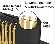
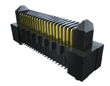
Figure 2: Edge Rate contacts are designed for high-speed, multi-cycle applications. Their smooth-milled, flat mating surface provides for increased durability and optimized signal integrity.
Mezzanine Strips feature rugged contact systems, slim bodies, and several low-profile stacking heights. Some include integrated ground planes. In this category, Samtec's Edge Rate contact system is designed for high-speed, high-cycle applications. The surface of the Edge Rate contact is milled, creating a smooth mating surface area instead of a stamped contact that mates on a cut edge. This smooth mating surface reduces the wear tracks on the contact, increasing the durability and cycle life of the contact system. It also lowers insertion and withdrawal forces, allowing the connectors to be zippered when unmating.
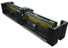
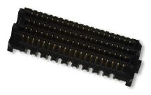
Figure 3: 0.635 mm Q2 High-Speed Rugged Ground Plane Socket Strip
Rugged High-Speed Strips offer increased insertion depths and designs for contact protection during mating and unmating. In this category, Q2 interconnects from Samtec are rugged, high-speed connectors featuring ground plane and high-wipe contacts. They have an integral power/ground plane. On 0.635 mm pitch, Q2 products have increased insertion depth for rugged applications, up to 156 signal pins/48 differential pairs standard, and are available in stack heights from 10-16 mm.
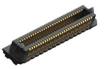
High-density arrays offer high performance, various pitches, stack heights, and configurations that allow routing, grounding, and design flexibility. It includes SEARAY open-pin-field arrays with pin counts up to 560, ultra-low profile compression one-pieces to super elevated 40 mm stack heights, and speeds up to 56 Gbps PAM4.
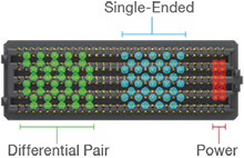
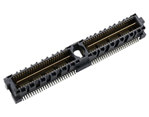
Figure 4a: SEARAY's open-pin-field design provides the ability to simultaneously run differential pairs, single-ended signals, and power through the same 28+ Gbps interconnect
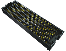
Figure 4b: .050" SEARAY High-Speed High-Density Open-Pin-Field Array Socket
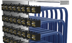
Figure 5: ExaMAX Backplane Cable System
Newer backplane solutions enable FPGA/SoC designers to optimize signal density in line card applications, such as data centers, while providing a path to 28 Gbps and beyond. This type of connector is engineered to increase data rates and decrease signal rise, delivering a more reliable high-speed transmission with greater clarity. In this category, high-speed ExaMAX traditional and direct-mate feature orthogonal systems for speeds up to 56 Gbps. High-density XCede HD features a small form factor and module design for system flexibility with 16 Gbps.
- 4.2 Mid-Board Optical Transceivers
Mid-board optics is critical in FPGA applications. Transferring high data rates over long lengths in lossy PCB materials can be challenging. Many OEMs continue to use approaches like CDRs and good SI/PCB layout techniques. However, flying that data over lossy PCBs via copper or optical cables is an approach the FPGA industry (and others) continues to adopt. At increased data rates, concerns about signal integrity over copper cable assemblies and connectors limit the reach and interoperability of systems.
The FireFly Micro Flyover System is the first interconnect system that gives a designer the flexibility of using micro footprint optical and copper interconnects interchangeably with the same connector system. The FireFly system enables chip-to-chip, board-to-board, on-board and system-to-system connectivity at data rates up to 28 Gbps. FireFly is based on a high-performance interconnect system which allows the use of low-cost copper cables or high performance active optical engines.
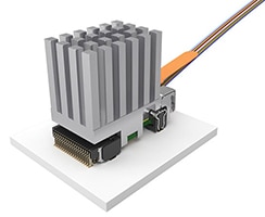
Figure 6: FireFly Active Optical Micro Flyover System Cable Assembly
FireFly Optical (ECUO) can support 14 Gbps, 16 Gbps, 25 Gbps, and 28 Gbps. These simplify board layout and enhance performance by taking data connection "off-board.” They occupy the smallest overall footprint, consume the least amount of power, and enable fast, easy, and low-cost fiber termination. They feature an integral heat sink in several default designs, including pin-finned (14 Gbps only), flat, fiber groove for multi-row configurations, and custom. The extended temperature FireFly, with a -40 °C to +85 °C range for military and industrial applications (ETUO), is also on display.
- 4.3 Front Panel Connectivity
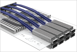
Figure 7: Flyover QSFP
Samtec Flyover Technology can also be used on the front-panel to mid-board, or mid-board to the backplane. For front panel connectivity, Samtec's Flyover QSFP Systems route critical high-speed signals through low-loss, ultra-low skew twinax cables instead of through expensive, potentially lossy PCBs to provide improved signal integrity and architectural flexibility. This cable system allows sideband signaling via press-fit contacts to improve airflow, reduce loss, and mitigate skew.
The Flyover QSFP28 (FQSFP) Cable System consists of the FQSFP assembly, the QSFPC cage, HS-QSFP heat sink, and LP-FQSFP light pipe. The routing through the FQFSP series permits designers to locate the QSFP interface much further from the ASIC or processor than traditional PCB routing would allow. This arrangement removes the need for expensive retimers or power-hungry drivers and receivers. The FQSFP series offers features including 28G NRZ/56G PAM4 data rates per channel, 3.5 W heat dissipation, and aggregate data rates of 100 Gbps NRZ/200 Gbps PAM4.
- 4.4 High-Performance Test for FPGA Transceivers
PCB-mounted SMA (Sub-miniature version A) connectors are traditionally used in transceivers on FPGAs. This approach has worked for decades, as transceiver counts per IC were low and PCB-mounted SMA connectors could support data rates in the megabit and reduced Gbps range. As standard transceiver speeds have pushed past 10 Gbps and transceiver counts increased, this approach proved impractical due to PCB size and cost constraints.
Samtec's Bulls Eye High-Performance Test System is replacing SMA technology in test and measurement systems. Compared to traditional PCB-mounted SMA connectors, it offers reduced board space, trace lengths, higher performance, and lower costs. Samtec has a new high-performance test assembly with performance up to 70 GHz (BE70A Series, Bulls Eye). It uses a single block design for ganged cabling and compression mount to the PCB, eliminating soldering and making it easier to install. The block is dual row, up to 16 contacts, and available for both microstrip and stripline transmission types. Bulls Eye has found additional uses in FPGA characterization, evaluation, and development boards.
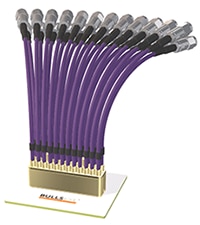
Figure 8a: 70 GHz, Bulls Eye: Double Row, High-Performance Test System
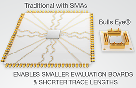
Figure 8b: Bulls Eye enables smaller evaluation boards and shorter trace lengths.
- 4.5 VITA 57.4 FMC+ Standard Products
VITA 57.4, also referred to as FMC+, is the latest Standard in the VITA FMC family. FMC and FMC+ standards are essential for FPGA suppliers making baseboards and comprehensive development kits to enable designers to accelerate their application development. FMC+ related products are used in industries such as datacom, broadcast, aerospace/defense, industrial, and instrumentation. FMC+ provides improved performance, faster data rates, and additional I/O while utilizing the same footprint as FMC.
Samtec's VITA 57.4 FMC+ HSPC Loopback Card (Figure 9a) provides FPGA designers with an easy-to-use loopback option for testing low-speed and high-speed multi-gigabit transceivers on any FPGA development board or FPGA carrier card. It can run system data or BER testing on all channels in parallel. This makes evaluation and development with an FPGA much more accessible and is an ideal substitute for 28 Gbps test equipment.
FireFly VITA 57.4 FMC+ Development Kits (Figure 9b) provide an easy connection between FPGAs and fiber optics. This solution offers an easy-to-use evaluation and development platform for FireFly optical engines. The 25/28 Gbps FireFly FMC+ Modules provide up to 400/448 Gbps full-duplex bandwidth over up to 16 channels from an FPGA/SoC to an industry-standard multi-mode fiber optic cable. The new kits support protocols including Ethernet, InfiniBand, Fiber Channel, and Aurora typically found in video, military/aerospace, embedded computing, instrumentation, HPC, and data center applications.
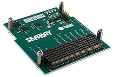
Figure 9a: FMC+ Loopback for FPGA Carrier Cards
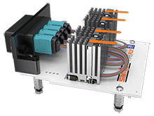
Figure 9b: 25/28 GBPS FireFly FMC+ Development Kit
5. Glossary
- CDR: The Clock Data Recovery system is used in serial communication of digital data for extracting timing information from a serial data stream.
- Crosstalk: Unwanted signals in a communication channel caused by transference of energy from another circuit, for example, by leakage or coupling.
- Electromagnetic compatibility (EMC): The ability of electrical equipment and systems to function acceptably in their electromagnetic environment by limiting the unintentional generation, propagation, and reception of electromagnetic energy.
- EMI: Electromagnetic interference is caused by one electrical or electronic device to another by the electromagnetic fields set up by its operation.
- FMC: An FPGA Mezzanine Card. It is a small mezzanine module optimized to provide the physical interface for FPGAs on a carrier card.
- HPC: High-performance computing is the ability to process data and perform complex calculations at high speeds.
- OEM: An original equipment manufacturer (OEM) is defined as a company whose goods are used as components in another company's products, which then sells the finished item to users.
- Parasitic capacitance: Unwanted capacitance that exists between the parts of an electronic component or circuit simply because of their proximity to each other.
- PCI Express (PCIe): Peripheral component interconnect express is an interface standard for connecting high-speed components.
- Phase-Locked Loop (PLL): An electronic circuit with a voltage or voltage-driven oscillator that constantly adjusts to match the frequency of an input signal. PLLs are used to generate, stabilize, modulate, demodulate, filter, or recover a signal from a "noisy" communications channel where data has been interrupted.
- PAM4: Pulse Amplitude Modulation 4-level is a multilevel signal modulation format used to transmit signals.
- Pitch: The spacing of the conductors. The pitch typically refers to the distance from the center of one conductor to the center of its neighboring conductor.
- QSFP interface: short for quad (4-channel) small form-factor pluggable, it is a compact, hot-pluggable transceiver also used for data communications applications.
- Signal Integrity (SI): It signifies the signal's ability to propagate without distortion.
- SMA (Subminiature version A): A coaxial cable connector developed as a semi-precision minimal connector interface with a screw-type coupling mechanism for coaxial cables.
- Surface mount technology (SMT): A method in which the electrical components are mounted directly onto a PCB.
*Trademark. Samtec is a trademark of Samtec Corp. Other logos, product and/or company names may be trademarks of their respective owners.
This learning module covers high-performance interconnect solutions that simplify interfacing to FPGAs. To extend the knowledge covered, the supplementary guide discusses the types of related components used for prototyping or product development.
Edge Rate
ERM8 is a board-mounted header designed for use in high-speed systems. It uses the Edge Rate contact system which is designed for applications requiring high-mating cycles and 56Gbps PAM4 performance. The ERM8 mates with ERF8 board-mounted sockets.
- Rugged Edge Rate contact
- Smooth broad milled contact surface for increased wear life
- 56 Gbps PAM4 performance
- SET Qualified Product
- Positions: Up to 200
- Stack Height: 7 mm - 18 mm
- Final Inch break out region data available
- 360° shielding available (ERM8-S)
- Latching, differential pair and extended guide post options
Q2 Series
These rugged, shielded, high-speed mezzanine connectors feature a ground plane and high-wipe contacts.
QMS-052-05.75-L-D-A Mezzanine Connector, Ground Plane, Header, 0.635 mm, 2 Rows, 104 Contacts, Surface Mount
Buy Now- Performance: Up to 8.5 GHz / 17 Gbps
- Increased insertion depth
- Dual stage hot pluggable
- Integral ground/power plane
- Shielded option available
- Power and RF ends options
- Contacts: Up to 208 I/Os
- Stack height: 10.00 mm - 16.00 mm
SEARAY
These high speed, high density, open-pin-field arrays allow maximum grounding and routing flexibility. They support 28+ Gbps applications and are also Final Inch certified for Break Out Region trace routing recommendations to save designers time and money.
SEAM-40-03.5-S-10-2-A-K-TRMezzanine Connector, High-Speed High-Density, Array, Male, 1.27 mm, 10 Rows, 400 Contacts
Buy Now- Maximum routing and grounding flexibility
- Lower insertion/extraction forces vs. typical array products
- Performance up to 28 Gbps NRZ/56 Gbps PAM4
- Up to 560 I/Os in an open-pin-field design
- 1.27 mm (.050") pitch and space saving 0.80 mm pitch
- Rugged Edge Rate contact system
- Can be "zippered" during mating/unmating
- Solder charge terminations for ease of processing
- Meets Extended Life Product (E.L.P.) standards
- 7 - 40 mm stack heights
- Vertical, right-angle, press-fit
- 85 Ω systems
- VITA 47, VITA 57, Pismo 2 certified
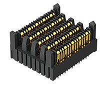
AcceleRate HD
AcceleRate HD ultra-dense, multi-row mezzanine strips are rated for 56 Gbps PAM4 on a 0.635 mm pitch. It features high-speed Edge Rate contacts designed for high-speed, high-cycle applications. The surface of the contact is milled creating a smooth mating surface, which reduces wear on the contact increasing durability and cycle life. Also, lower insertion and withdrawal forces allow zippered unmating. Incredibly dense with up to 240 total I/Os; up to 400 in development.
- Low profile 5 mm stack height
- Slim 5 mm width
- 4-row design; 10 - 60 positions per row (70 - 100 total positions per row in development)
- Open-pin-field design for grounding and routing flexibility
- Supports 56 Gbps PAM4 (28 Gbps NRZ) applications
- PCIe Gen 5 compatible
- Solder ball technology for simplified processing and self aligning
- 7 - 16 mm stack heights, right-angle and cable in development
FireFly Micro Flyover System
UCC8 Series connectors are designed to work specifically with the FireFly flyover system.
UCC8-010-1-H-S-1-A PCB Receptacle, Wire-to-Board, 0.8 mm, 1 Rows, 10 Contacts, Through Hole Mount, UCC8 Series
Buy Now- Connector Systems: Wire-to-Board
- Pitch Spacing: 0.8mm
- No. of Rows: 1 Row
- No. of Contacts: 10 Contacts
- Connector Mounting: Through Hole Mount
- Contact Material: Beryllium Copper
- Insulator Material: Black LCP
- Current Rating: 1.8 A per pin
- Operating Temp Range: -55 ° C to +125 ° C
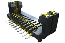
MPOWER
The mPOWER connector system is a micro, high-power solution with incredible design flexibility for power-only or power/signal applications. Due to the wide variety of stack heights available, mPOWER can be easily added to new or existing architectures alongside one of Samtec's high-speed connector systems for a unique two-piece power and signal/ground solution.
UMPT-04-06.5-G-VT-SM-WT-K Pin Header, Power Terminal, Board-to-Board, 2 mm, 1 Rows, 4 Contacts, Surface Mount Straight
Buy Now- Design flexibility as a two-piece system for power/signal applications
- Up to 18 A per power blade
- 2 – 10 power blades on a 2.00 mm pitch
- SET Qualified Product
- 5 mm to 16 mm, 18 mm and 20 mm stack heights
- Use with Samtec's high-speed connector systems including: Edge Rate, AcceleRate HD, Q Strip, Q2, Q Rate, LP Array, SEARAY, SEARAY 0.80 mm, Tiger Eye, Ultra Micro Blade & Beam
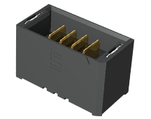
EXAMAX
ExaMAX high-density backplane systems offer design flexibility to fit a variety of applications, including Flyover cable supporting 112 Gbps PAM4 and board-to-board supporting 56 Gbps PAM4. The ExaMAX contact system achieves two reliable points of contact at all times, and minimizes residual stub for improved signal integrity performance, while providing low mating force and excellent contact normal force. Signal wafers incorporate a one-piece, embossed ground structure which improves crosstalk.
- 4 or 6 pairs per column
- 2.00 mm (.0787") pitch
- Press fit termination
- Insulator Material: Liquid Crystal Polymer
- Contact Material: Copper Alloy
- Plating: Sn or Au over
- 50 µ" (1.27 µm) Ni
- Operating Temp Range: -55 °C to +105 °C
- Current Rating: 4.2 A per pin
- Contact Wipe: 2.4 mm
For more high-performance interconnects products Shop Now
Test Your Knowledge
Connectors VIII

Are you ready to demonstrate your knowledge of High Performance Interconnects for FPGA Applications? Then take a quick 10-question multiple choice quiz to see how much you've learned. To earn the Connectors VIII Badge, read through the learning module, attain 100% on the Quiz, and leave us some feedback in the comments section.
Top Comments