1. Introduction | 2. Objectives | 3. Basic Concepts | 4. Analysis | 5. Glossary | Related Components | Related Tech Spotlight | Take the Quiz
Advanced technologies such as cloud computing and the Internet of Things (IoT) demand fast, secure, and high-capacity data transmission. Fiber optics enable the communication of data over long distances with minimal losses during transmission, and with higher connection speeds for multiple users. The integration of fiber optics and wireless communication (known as "last mile" access) benefits both service providers and users alike, by minimizing deployment costs, shortening the upgrade period, and increasing mobility and flexibility of broadband services access. This learning module covers the fundamentals of fiber optic communication, its components, and applications.
2. Objectives
Upon completion of this module, you will be able to:
- Understand the basic concepts of fiber optics
- Discuss the applications of fiber optic communications
- Differentiate between residential fiber Internet and business fiber Internet
- Understand the various connectors and cables used in optical fiber communication
In a fiber optic communication system, electronic signals are converted into pulses of light and transmitted over fiber. Modern systems can be extraordinarily complex, with large numbers of channels being transmitted over long distances at high transmission rates. To understand the operation of a fiber optic data transmission system, we will first review fundamental theories associated with fiber optics.
- Electromagnetic Theory of Light
Light is an electromagnetic wave phenomenon (explained by Maxwell’s Equations). Its electric and magnetic components are mutually perpendicular to the direction of light travel (Figure 1). Optical frequencies occupy an electromagnetic spectrum band that extends from the infrared through the visible to the ultraviolet.
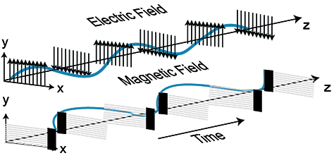
Figure 1: The Structure of an Electromagnetic Wave
- Total Internal Reflection and Critical Angle
A light ray can travel down plastic or glass fiber and bend around corners because of refraction. A light ray bends towards the normal when it crosses an interface into a medium having a higher refractive index. Conversely, a ray of light bends away from the normal when it cuts across an interface from a higher refractive index medium to a lower refractive index medium.
Referring to Figure 2, when incidence angle θ1 increases, θ2 also increases. At a certain angle (θc), the refracted wave will travel along the surface between the two mediums (air and glass). θc is known as the critical angle, where: sin θc = (n2/n1)
Plastic or glass fibers have a core and cladding with differing refractive index. If the angle of the light traveling through the fiber is less than the critical angle, the light will be reflected by the internal surface of the fiber and continue on its path (as illustrated by the blue line in Figure 2). If the angle of light is too large, the light will escape through the surface of the fiber and be lost (as illustrated by the green line). In order to effectively keep the light signal inside the fiber when it travels around a corner, the curve of the fiber cannot exceed its maximum bend radius, typically ten times the diameter of the cable.
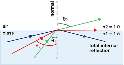
Figure 2: Critical Angle and Total Internal Reflection
- Acceptance Angle and Numerical Aperture
The acceptance angle of an optical fiber is the maximum angle of a ray hitting the fiber core, which permits the incident light to be guided by the core. The sine of that acceptable angle is termed the numerical aperture (NA).
The numerical aperture of a fiber represents its light-gathering capability. The larger the numerical aperture, the greater the amount of light accepted by the fiber.
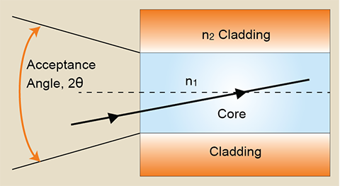
Figure 3: Acceptance Angle and Numerical Aperture
- Basic Structure of an Optical Fiber
Figure 4 represents the typical structure of a fiber used for communication links. The fiber is lightweight and has minimal loss, making it ideal for information transmission over long distances. An optical fiber is comprised of the following:
- Core: a dielectric cylinder of single solid construction. The core has a refractive index n1.
- Cladding (as a rarer medium): a solid dielectric cladding that encircles the core and has a refractive index n2 < n1. Cladding reduces the scattering losses that occur due to dielectric discontinuities at the core surfaces. It also provides mechanical strength to the fiber. The cladding is typically made of glass or plastic.
- Buffer: a polymer material that encapsulates most fibers and adds further mechanical strength to the fiber.
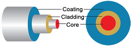
Figure 4: Basic Structure of an Optical Fiber
- Types of Optical Fiber
A single-mode fiber has a smaller core diameter and can support only one mode of propagation. A multimode fiber has a core diameter greater than 50 μm, and can support multiple modes. Multimode fibers are further distinguished based on index profile:
- Single Mode Step Index fiber: A single more stem index fiber has a super fine, thin core with a uniform refractive index of a higher value, surrounded by a cladding of a lower refractive index. In step-index fiber, the refractive index changes abruptly at the core-cladding boundary. An opaque protective sheath encloses the fiber. A typical single-mode step-index fiber has a core diameter of 4 µm or microns.
- Multimode Step Index fiber: A multimode step index fiber resembles the single mode step index fiber except that its core has a bigger diameter. A typical multimode step index fiber has a core diameter of 100 µm or microns. Light follows zigzag paths inside the fiber, enabling many of these propagation paths to be possible. The NA of a multimode step-index fiber is larger as the core diameter of the fiber is larger.
- Multimode Graded Index fiber: A graded index (GRIN) fiber is a multimode fiber with a core consisting of concentric layers of materials with different refractive indices. The refractive index of the core varies with distance from the fiber axis, higher at the center and falling off with increasing radial distance from the axis. In the case of GRIN fibers, the acceptance angle and NA decrease with radial distance.
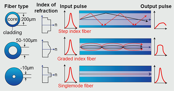
Figure 5: Types of Optical Fiber
- Dispersion in Optical Fiber
Optical data signals are comprised of concise pulses of light, which become longer in duration or broaden when they are transmitted through the fiber. Such broadening causes the pulses to overlap in a sufficiently long fiber, causing mutual interference, which can hamper the receiver’s ability to resolve the transmitted data and result in bit errors. This phenomenon is called dispersion, and can limit the bandwidth and distance of the transmission. Dispersion is classified into two categories:
- Modal dispersion: With its large core diameter, multimode fiber can guide many different spatial light modes. These fields are reflected off the cladding wall at different angles, causing them to travel disparate distances and propagate down the fiber at different speeds. The optical pulses broaden because they exit the fiber at different times.
- Chromatic dispersion: Different wavelengths of light propagate at slightly different velocities through the fiber. This causes the light pulses to spread. Because an optical fiber consists of core and cladding of materials with different refractive indexes, some wavelengths will travel slower or faster than others.
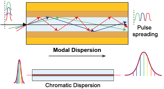
Figure 6: Dispersion in Optical Fiber
- Fiber Optic Transmission System
- Transmitter: The transmitter converts the electrical input signal into an optical signal. The transmitter's drive circuit achieves this by varying the current flow through the light source, which in turn varies the irradiance of the source. Light-emitting diodes (LEDs) and semiconductor laser diodes are the most commonly used devices.
- Optical Fiber cable: The optical fiber acts as a waveguide and uses the principle of total internal reflection to transmit the optical pulses toward the receiver.
- Amplifiers: Since absorption, scattering, and dispersion in the fiber degrade the signal, optical amplifiers are required for signal regeneration. With current technology, repeaters and amplifiers are required every few kilometers.
- Receivers: A receiver converts the optical signal exiting the fiber into an electrical signal. The receiver consists of an optical detector and a signal-conditioning circuit. The optical detector can be either a semiconductor PIN diode, whose electrical conductivity is a function of the intensity and wavelength of the light signal, or an avalanche photodiode detector.
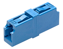
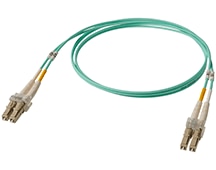
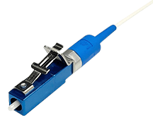
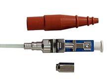
- Connectors: An optical fiber connector connects the two end faces of the optical fiber in a precise manner, ensuring that the strength of the transferred signal is maximized. The most popular optical fiber connectors are as follows:
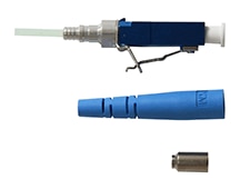
- LC Connector - The Lucent connector (LC) is a small form factor connector with a 1.25 mm ceramic ferrule. The snag-free latch enables easier insertion and allows consistent connections.
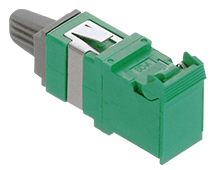
- SC Connector – A Square push-pull connector (SC) has a square-shaped connector body with a 2.5 mm ferrule. SC fiber optic connectors are suitable for CATV, FTTH, LAN, MAN, and WAN applications, including point-to-point and passive optical networking.
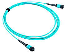
- MTP/MPO Fiber Connector – A MTP/MPO (Multi-fiber Termination Push-on/Multi-fiber Push On) connector is a multi-fiber connector that is larger than other connectors, combining 12 to 24 fibers in a single rectangular ferrule. It finds use in 40G and 100G high-bandwidth parallel optical connections.
- ST Connector – An ST (Straight Tip) connector features a 2.5 mm ferrule with a quick-release bayonet-style body.
- FC Connector - An FC connector is a screw-type connection that utilizes a cylindrical metal coupling nut with keyed sleeves. FC connectors use a 2.5mm ceramic ferrule and have a pull-proof mechanism for increased durability.

Figure 7: A Fiber Optic Transmission System
- Optical Network
A network enables users and devices to communicate with each other by transporting information from a source to a destination. Intermediate stages that process data for control operation may also be required. Figure 8 illustrates the structure of a simple optical network. It consists of optical nodes, which are interconnected with optical fiber links. An optical node is a multifunctional element that acts as a transceiver, which receives, transmits, and processes the optical signal. Optical fibers provide point-to-point physical connections between network nodes. The point-to-point fiber links can be used to establish logical links where the destination node can be reached by traveling through one or more intermediate nodes in a single or multiple hops.
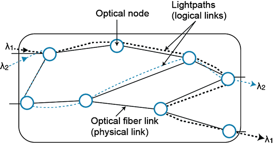
Figure 8: Optical Network Structure
- Applications of Fiber Optic Cable
Fiber optics have transformed and advanced numerous industries, including the Internet, computer networking, telephone, and television networks. More recently, fiber optics have revolutionized data centers, wireless, and cloud providers that send and manage vast amounts of data. Some of the most used application areas are:
| Transportation Systems | Railways - communication, signaling, and command-dispatching, as well as entertainment applications, such as onboard Internet, and passenger information systems Roadways - Traffic cameras, connected vehicles, automated License Plate Recognition, telematics, and traffic signals |
| Medical Surgery and diagnosis | Remote testing and diagnostics, robotic procedures, imaging, spectrophotometry, position sensing, and endoscopy |
| Electrical Power Systems | Monitoring and controlling power grid systems |
| Networking and Media Devices | Modern IP cameras, video encoding, network video recording, network switches, home theater, and sound systems |
| Industrial Automation | Industrial and warehouse robotics, communication between field devices, sensors, actuators, and controllers |
- Residential Fiber Internet vs. Business Fiber Internet
The key differences between business and residential fiber internet are:
| Business Fiber Internet | Residential Fiber Internet |
|---|---|
| 1. Comes with Service Level Agreement (SLA) and offers guaranteed bandwidth, uptime, and less mean time to repair (MTTR). | 1. Does not come with SLA and offers no guarantee for speed and high MTTR. |
| 2. Offers static IPs for hosting network infrastructure, including file and mail servers. Static IPs are more reliable and secure | 2. Dynamic IPs are the standard. They move and change without notice, making it difficult for hosting servers and other network devices. |
| 3. Business fiber is symmetrical (upload speed is equal to download speed). Symmetrical connections are crucial for businesses that back up data to offsite centers. | 3. Residential internet usage is dominated by streaming video/music and web surfing. Residential Internet is usually asymmetrical, with faster download speeds than upload. |
| 4. Business Internet most likely uses a Point-to-Point (P2P) connection, which results in faster speeds, less latency, and reduced packet loss. | 4. Residential Internet is a Point-to-Multipoint (PMP) system, resulting in slower speeds, more latency, and packet loss. |
- Angled Physical Contact (APC): a connector with an angled tip to reduce optical signal reflections at the fiber mating surface
- Asymmetrical Internet connection: an Internet connection with differing upload and download speeds. Typically, the upload speed is lower than the download speed.
- Bandwidth: the information-carrying capacity of an optical fiber, measured in MHz-km and GHz-km
- CATV (Community Access Television): a method of transmitting television signals to a consumer's home, using radio frequency signals transmitted through coaxial cable
- dB: abbreviation for decibel, the unit of measurement for optical power in a fiber optic cabling system
- Dynamic IP address: an IP address that might change over time
- EMI (electromagnetic interference): interference in signal transmission or reception resulting from electrical or magnetic field radiation
- Ferrule: a tube within a connector, with a central hole that holds and aligns a fiber
- LASER (Light amplification by simulated emission of radiation): a device that emits a beam of light using an optical amplification process
- Local area network (LAN): a collection of devices connected together in one physical location, such as a building, office, or home
- Mean time to repair (MTTR): a maintenance metric that measures the average time required to troubleshoot and repair failed equipment
- Metropolitan area network (MAN): a network that interconnects users with computer resources in a geographic region the size of a metropolitan area
- Modulation: the process by which the characteristic of one wave (the carrier) modifies another wave (the signal)
- Normal (Normal ray or line): a light ray that is perpendicular to a reflecting surface
- PIN diode: a diode with a wide, undoped intrinsic semiconductor region between a p-type semiconductor and an n-type semiconductor region
- Point-to-multipoint communication: a type of network topology where a channel is shared by multiple nodes or devices
- Point-to-point connection: a network topology where there is a dedicated communication link between two nodes or devices
- Static IP address: an IP address that does not change
- Symmetrical Internet connection: an Internet connection with equally fast download and upload speeds
- Wide-area network (WAN): a network that connects a large geographic area. A WAN connects many smaller networks, including LANs and MANs
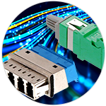
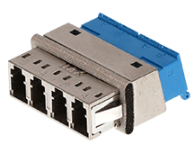
Fiber optic cable assemblies typically come with the proper connectors attached to the ends of the cable. The connector type is dependent on the type of optical fiber and the intended use of the assembly. Molex offers fully customizable optical fiber cable assemblies and harnesses, which provide rugged, flexible, cost-effective, and competitive optical cabling solutions, well-suited for use in industrial and consumer electronics applications.
Take the QuizBack to Top
Fiber Optics 1
Complete our Essentials: Fiber Optics 1 course, take the quiz, and leave your feedback to earn this badge.


