Audio I: Microphone Essentials
1. Introduction | 2. Objectives | 3. Basic Concepts | 4. Analysis | 5. Glossary | Related Components | Take the Quiz
Sound is a form of energy created by vibrations that move through the air, or other medium, as an acoustic wave. The faster the vibration, the higher pitched the sound will be. A healthy human ear can detect frequencies from 20 Hz to 20 kHz; however, there are many sounds that exist in the frequencies outside of human hearing. Dogs, for example, can detect frequencies up to approximately 60 kHz.
Microphones are devices that are used to convert acoustic energy into electrical energy. Most microphones are designed to record sounds for music, entertainment, and broadcast, and do not need to capture more than the frequencies that humans are able to hear. Frequencies above human hearing range, however, have great importance to scientists and engineers, and measurement microphones can have a frequency response that goes from 1 Hz to as high as 140 kHz. This learning module discusses various types of microphones, their working principles, and their characteristics.
2. Objectives
Upon completion of this module, you will be able to:
- Describe how sound is captured in a microphone
- Discuss the various types of microphones
- Understand the specifications of microphones
- Explain pickup patterns in microphones and how to achieve them
Sound travels through a medium when the vibrations of an object cause adjacent particles to vibrate, which in turn, cause the particles next to them to vibrate. The vibration travels through the air as a pressure wave with similar frequencies to the original source. A microphone detects these pressure waves and converts them into an electric signal, which can be recorded, analyzed, and processed. This mechanism is similar to that of a human eardrum.
Sound waves create a pressure that can be measured and recorded. Sound pressure level (SPL) is expressed in pascals (Pa) or decibels (dB), and represents the strength at which a receiver perceives sound. Sound levels can also be measured as sound power, which is expressed in watts (W). SPL expresses the total acoustic energy that the source radiates in all directions, independent of the environment. Sound power only measures the source, while sound pressure takes into consideration the reflecting surfaces, ambient sounds, and distance to the receiver.
There are many different types of microphones designed for a variety of applications. Some microphones are designed to record voice, musical instruments, or sound effects. Others are designed for measurement. Each application has its own set of performance requirements.
- Pressure Microphones

Figure 1: Working principle of a pressure microphone
The basic construction of a pressure microphone is a thin, moveable diaphragm in front of a closed chamber. A sound wave reaches the diaphragm from one side, generating movement in the diaphragm due to the differing pressures on either side. An increase in pressure will move the diaphragm inward, while a decrease in pressure causes the diaphragm to move outward. Pressure microphones are omnidirectional and will detect sound no matter what direction it is coming from. The microphone’s physical dimensions affect frequency response; an increase in the size of the diaphragm and chamber increase corresponds to increased sensitivity lower down in the frequency range.
- Pressure Gradient Microphones

Figure 2: Working principle of pressure gradient microphone
The diaphragm in a pressure gradient microphone reacts to sound waves from both sides. The difference in pressure between the front and back, or pressure gradient, is proportional to the output voltage of the microphone. Sound that comes from the side does not affect the pressure on the front and back of the diaphragm; thus, pressure gradient microphones have a Figure-8 directional pattern (directional patterns will be covered later).
The pressure gradient changes with frequency. Lower frequency sounds have a longer wavelength, which results in a smaller pressure gradient. As the frequency increases, the movement of the diaphragm increases, resulting in higher and higher pressure gradients. The maximum pressure gradient occurs at the frequency where half the wavelength is equal to the distance between the front and back of the diaphragm. This frequency is typically approximately 5-10 kHz in standard-sized microphones.

Figure 3: Pressure gradient as frequency changes
To achieve a flatter frequency response in a pressure gradient microphone, different techniques can be used. One such technique is to “tune” the diaphragm by reducing its tension, resulting in more low-frequency sensitivity. This technique is similar to tuning a drum to raise or lower pitch.
Pressure gradient microphones also exhibit a characteristic called proximity effect. The closer the source is to the microphone, the greater the low frequencies that are captured. Proximity effect occurs only at short distances and follows the inverse square law; 6 dB are lost every time the distance from the source is doubled.
- Combined Pressure and Pressure Gradient Microphones

Figure 4: Sound enters the housing from the front and rear, combining pressure and pressure gradient techniques.
Combining pressure and pressure gradient techniques allows designers to create a microphone that is directional. A directional microphone is capable of picking up sound from a targeted space around it. Microphone directionality and pickup patterns will be discussed later.
The sound waves that affect the back of the diaphragm enter through openings in the housing of the microphone. These openings can be varied to change the pickup patterns of the microphone. Blocking or damping the rear opening attenuates sounds coming from directly behind the microphone, giving it increased sensitivity in all other directions (cardioid pattern). The amount of attenuation can be adjusted to change the shape of the pickup pattern.
- Converting Sound Pressure to Electric Signal
There are several different types of microphones, each with their own way to convert the movements of their diaphragms into electrical signals.
- Dynamic Microphones
Dynamic microphones convert sound pressure into an electrical signal using electromagnetic induction. Inside the microphone capsule, a permanent magnet creates a magnetic field around an electrical conductor. Sound pressure causes the electrical conductor to move, and the presence of a magnetic field creates a voltage. This voltage is amplified to a mic-level signal using a transformer.

Figure 5: Working principle of a dynamic moving coil microphone
In a moving coil microphone, the electrical conductor is a small coil attached to a diaphragm made of plastic or metal. Moving coil microphones have a resonant frequency, typically between 150 and 800 Hz. As such, the diaphragm must be dampened in order to achieve as flat of a frequency response as possible.
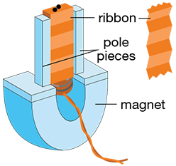
Figure 6: Ribbon Microphone
A ribbon microphone uses as its conductor a thin metallic tape suspended between the poles of the magnet. Movement in the ribbon generates voltage across its ends, which is amplified by a transformer. Resonant frequency is determined by the mass of the ribbon, which is typically less than 0.5 mg. Because of the loosely suspended ribbon, ribbon microphones are sensitive to mechanical impact and wind.
- Condenser Microphones

Figure 7: Working principle of condenser microphone
A condenser microphone consists of two charged parts: a flexible, moveable diaphragm stretched in front of a fixed back electrode or backplate. When a bias voltage is supplied, an electric field is present between the diaphragm and backplate (similar to the plates in a capacitor). Sound pressure causes the diaphragm to move, changing the distance between the diaphragm and backplate, creating a change in voltage. Condenser microphones are often capable of using phantom power, a mechanism whereby DC power is transferred to the microphone using the same cable as the audio signal.
A condenser microphone’s diaphragm is typically a plastic foil with a vapor-deposited metal layer, 3-6 µm thick. Small diaphragm condenser microphones (typically around 12.7 mm or less) capture sound more accurately, with fast transient response, extended high frequency response, and consistent pickup patterns. Small diaphragm condensers are widely used as measurement microphones. Large diaphragm microphones have a more flawed frequency response; however, these flaws shape the sound in a pleasing manner, flattering the voice and many musical instruments.
- Electret Microphones

Figure 8: Working principle of an electret microphone
Electret microphones work in a similar manner to condenser microphones, with one exception: electret microphones do not require an external bias voltage. Instead, an electret microphone uses materials that are electrically polarized in advance. Examples include plastic foils, such as polyester, PVC, or Teflon, or ceramic. Electret materials are polarized by being heated, then placed in an electrostatic field during cooling, after which, the material retains the electric charge.
- Carbon Microphones

Figure 9: Working principle of a carbon microphone
A carbon microphone is a lower quality, more value-oriented design. It uses a diaphragm in front of a housing containing lightly packed carbon granules. The housing has electrical contacts that have a known resistance. In the presence of sound pressure, the granules are pressed together, decreasing the resistance at the contacts. This change in resistance can be measured. This design was used in early telephone designs.
- Piezoelectric Microphones
Piezoelectric or crystal microphones use a quartz or manmade ceramic crystal structure, which have a permanent polarization. A thin piezoelectric diaphragm is attached to a brass or alloy disc. The voltage difference across the two pieces is amplified to produce an electric signal. Piezoelectric microphones are not used to detect sound waves in air, but sound that is generated by contact with solid objects. They are often referred to as contact microphones.
- MEMS Microphones
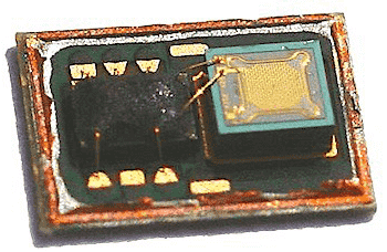
Figure 10: A MEMS microphone with protective cover removed. Image Source: mynewmicrophone.com
A MEMS (Micro-Electro-Mechanical-Systems) microphone is a tiny microphone produced using MEMS techniques. The entire microphone system, typically including onboard preamps and analog-to-digital (AD) converters is etched onto a silicon wafer. A MEMS microphone works in a similar fashion to a condenser microphone; a pressure-sensitive, moveable diaphragm is etched behind a stationary plate. The two layers work together to form a capacitor that responds to sound pressure. The components of a MEMS microphone are enclosed in a protective case with a small hole to allow sound to pass into the microphone element.
- Directional Patterns
A directional pattern is a visual representation of the areas from which the microphone captures or rejects sound. In some applications, microphones are required to capture sound from the front and sides, rejecting everything behind (cardioid pattern). In other situations, a microphone needs to capture all of the audio surrounding it (omnidirectional pattern). In some applications, such as recording dialogue on location or in the field, a microphone needs to have a very narrow focus, capturing only the actor’s voice and rejecting all other noises, including room reflections (hypercardioid pattern). Figure 11 illustrates the various directional patterns in linear and log scale.
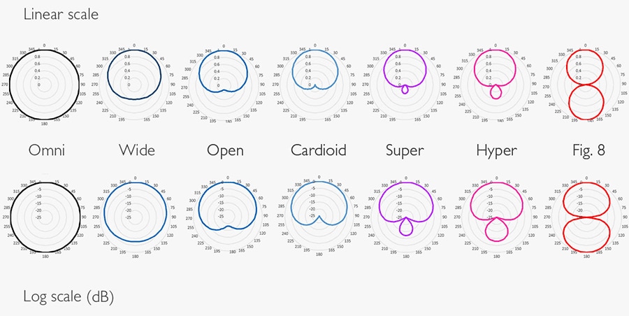
Figure 11: Directional patterns of microphones. Image Source: www.dpamicrophones.com
Directional patterns can be achieved with a combination of housing design and, in the case of a dual diaphragm condenser microphone, adjusting the sensitivity and polarity of the diaphragms. Dual diaphragm condenser microphones are essentially two cardioid capsules mounted back to back. To achieve the desired patterns, the following adjustments can be made:
- Cardioid: The microphone picks up sounds from the front and sides, and rejects sounds from the rear. With cardioid, the rear capsule is off (or the gain is heavily attenuated) and only the front capsule is active
- Omnidirectional: The microphone picks up sounds from all directions. With an omnidirectional pattern, both capsules are on, and equal in polarity and gain
- Figure-8: The microphone pics up sounds from the front and the rear, equally, and rejects all sounds from the sides. In figure-8 mode, both capsules have equal gain, however the polarity is reversed
- Hypercardioid: The microphone picks up sounds from the front, but in a much narrower pattern than cardioid. Some sound is picked up from the rear. With hypercardioid, polarity of the two capsules are reversed, and the gain on the rear capsule is attenuated
Integrating housing design to achieve directional patterns was touched on briefly earlier; however, for special applications, there are additional housing designs that enable even more directionality.
- Interference Tube Microphones
An interference tube microphone, often referred to as a “shotgun” microphone, offers a pickup pattern that is more focused than the hypercardioid pattern.

Figure 12: Interference tube microphone
The diaphragm of an interference tube microphone sits behind a long hollow tube. The tube is typically a single mesh tube, covered by a hard-shell with several slits. Desired sounds enters the tube directly on axis and travels directly to the diaphragm. Undesired off-axis sounds enter via multiple slots on the side. Because there are several different distances from the slots to the diaphragm, the undesired sound arrives at the diaphragm with differing phase relationships, causing cancellation and attenuation. More of the desired sound remains.
While an interference tube microphone has most of its sensitivity in one direction, off-axis sounds that don’t cancel can cause strange artifacts and color the sound. As such, interference tube microphones are not recommended for use in small rooms or highly reverberant locations.
- Zoom Microphones
A zoom microphone combines a high-directivity interference microphone with a pressure gradient microphone in the same housing. The microphones can be shifted to be closer or farther away from each other, achieving a variable directional factor.
- Boundary Layer Microphones
A boundary layer microphone is essentially a microphone element placed on top of a hard surface. If a sound hits the hard surface, it reflects directly into the microphone, increasing the sound pressure level (SPL) by 6 dB. Diffuse sounds gain only 3 dB. The 3 dB free field-to-diffuse ratio gives this type of microphone the ability to draw in distant sounds.
- Microphone Specifications
With so many different types of microphones, many different types of specifications exist to characterize them. The following guide will help with evaluating and comparing microphones based on their specifications.
Most specifications are expressed in dB, or decibels. The decibel scale isn’t linear, but rather logarithmic, because human hearing is closer to being logarithmic. 1 dB is the smallest perceptible change in audio level, while 3 dB is an obvious change. A 10 dB change is perceived as a doubling (or halving) of the audio level. One notable characteristic of the decibel scale is that it is a relative scale, and expresses the difference between two levels. Applying a reference makes dB an absolute scale. Referencing a 20 µPa noise floor (approximately the threshold of human hearing) means that 0 dB corresponds to 20 µPa. This measurement can then be expressed in units of “dB re 20 µPa” or “dB SPL” (though many manufacturers simply use “dB”. In electrical terms, the unit “dBV” is often used, which signifies that the reference is 1 Volt. Microphone sensitivities are often expressed in dBV.
- Microphone Sensitivity
A microphone’s sensitivity describes the amount of output voltage it delivers for a specific sound pressure level. It is often called free-field sensitivity, which is the amount of output voltage when the microphone is placed in a free-field (a space where no sound reflections occur) and exposed to an on-axis sound of 1 Pascal (or 94 dB). The signal from high sensitivity microphones require less amplification; however, in applications with high SPLs, a lower sensitivity microphone may be more suitable in order to avoid overloading the circuits that follow.
- Frequency Response
The frequency response shows the frequency range that the microphone is sensitive to. Measurement microphones typically have a flat frequency response (approximately the same output for all frequencies across the range), while microphones designed for voice or musical instruments might have a response where certain frequencies are boosted or reduced to present the source in a more pleasing manner. For example, boosting frequencies in the 1 kHz to 4 kHz range increases intelligibility in voices.

Figure 13: Frequency response of a DPA Microphones 4006 Omnidirectional Microphone
Microphones with multiple patterns typically publish the frequency response for each pattern, as they will all be slightly different from each other.

Figure 14: On- and off- axis frequency responses for DPA Microphones 4011 cardioid microphone
On-axis response describes how the microphone picks up sounds that are directly in front of it. Off-axis response describes how the microphone reacts to sounds coming from different angles. Figure 13 illustrates on- and off- axis responses for a cardioid microphone (DPA Microphones 4011). Diffuse field response describes the way an omnidirectional microphone will pick up sound in a reverberant sound field, where reflections are almost as strong as the direct sound.
- Total Harmonic Distortion (THD)
The distortion of a microphone is specified with THD < 1%, which is the maximum SPL below which the total harmonic distortion is less than 1%. Distortion can occur at the diaphragm (if the SPL causes the diaphragm to move past its limits) or in the electronics that follow.
A microphone’s dynamic range is dependent on THD. Dynamic range is the difference between a microphone’s THD < 1% and the self-noise of the microphone.
- Maximum SPL
A microphone’s maximum SPL, also called the overload SPL, describes the loudest sound a microphone can handle. Typically, this is the SPL where the microphone reaches a total harmonic distortion (THD) level of 10%.
- Ambient noise: the background or surrounding noise of a location, where no foreign excitation is present.
- Attenuation: the reduction in the level of an electrical or acoustic signal.
- Cardioid pattern: a microphone pickup pattern that picks up the sound in front and on the side, and rejects sounds from the rear.
- Decibel (dB): a unit on a logarithmic scale, which measures the level of a sound wave or electrical signal by comparing it with a reference level.
- Diaphragm: the component in a microphone that moves in response to sound pressure. Can also be called the membrane.
- Diffuse sound: sound that does not originate from a single source or direction, and is random in phase.
- Distortion: the changing or deformation of the original waveform of an audio signal that is the result of non-linearity in the device.
- Dynamic range: the range between the quietest and loudest levels a device can produce or detect. For a microphone, the quietest level is typically its self-noise, while the loudest level is the level that causes a specified amount of distortion.
- Equivalent noise level: the self-noise of a microphone.
- Figure-8 pattern: a microphone pickup pattern that picks up sound from the front and the rear, and rejects sounds coming from the sides. Also known as bidirectional pattern.
- Free field: a space where there are no reflective surfaces within a specified frequency range.
- Frequency: the number of waves per second, measured in Hertz (Hz). Lower frequencies produce more bass-y sounds, while higher frequencies produce higher pitched sounds.
- Frequency response: a graph that shows what the output of a microphone (or other audio device) will be over a given frequency range.
- Hypercardioid pattern: a microphone pickup pattern that picks up sound from a narrow area in front, with a small amount from the rear. Useful for isolating desired sounds and rejecting unwanted ones.
- Noise floor: the level of the signal that is a sum of all noise sources and unwanted signals in an audio system or environment.
- Omnidirectional pattern: a microphone pickup pattern that picks up sounds in a 360° radius. An omnidirectional mic is sensitive to sounds coming from all angles.
- Phantom power: a method of supplying power to a condenser microphone through the microphone cable. Half of the DC power flows through each signal conductor and returns to the source through the cable's shield.
- Polar pattern (or directional characteristics): a visual representation of a microphone's response to sounds from various angles surrounding it. Also used for speakers.
- Proximity effect: the increase in low frequency sounds when the microphone is positioned very close to the source of the sound.
- Sensitivity: a microphone's output voltage when exposed to an SPL of 94 dB.
- Total harmonic distortion (THD): a measure of the sum of the harmonic distortion present in a signal, expressed as a percentage of the fundamental.
Microphones are used in a variety of industries, including industrial and medical applications, where sound can be used to detect anomalies. Several technologies are used to detect sound pressure; some achieve a flat frequency response, while others strive for a more euphonic, flattering sound.
Take the QuizBack to Top

Are you ready to demonstrate your microphone essentials knowledge? Then take this 10-question quiz. To earn the Audio I Badge, read through the module, attain 100% in the quiz, and leave us some feedback in the comments section.


