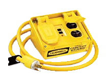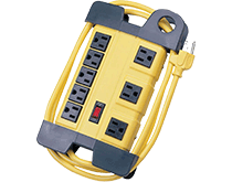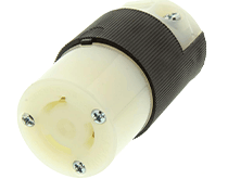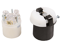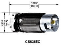
Grounding is a wiring connection that provides a path for short circuit current to be sent to earth ground when a fault in the electrical power systems occurs. In this respect, grounding is a safety measure that connects electrical circuits or equipment to a reference point to ensure safety, prevent electrical faults, and maintain stable voltage levels. This Essentials course explores the significance of grounding: its purpose, types, and safety considerations. Using Hubbell wiring devices as an example, we will highlight product applications and illustrate the importance of grounding for safety, equipment protection, and system reliability.
Related Components | Test Your Knowledge
2. What is Grounding?
Grounding is the practice of connecting a conducting object or system to the Earth or to a common reference point, ensuring device safety, stability, and to prevent electrical interference and damage. The practice is known as ‘grounding’ because the electricity is guided to the ground where it can discharge. Grounding provides a pathway for electrical currents to safely dissipate in the event of a fault or surge, reducing the risk of electric shock, fires, and equipment damage. Without grounding, electricity can build up, potentially leading to arcing. Electrical systems, appliances, and metal enclosures are connected to ground as a reference point and return path for current.
The Importance of Grounding
By first knowing what grounding is, we can then start to understand why it is so important. Grounding is used to:
- Prevent electrical shock hazards
- Protect equipment from damage caused by voltage surges
- Shield equipment from lightning strikes and electromagnetic interference
- Stabilize voltage levels in electrical systems
- Provide a fault current path, such as a short circuit, in the event of a fault
Important Terminology – Types of Grounding
In the context of electronics, grounding can refer to several things. While the general idea is the same, grounding can have different meanings when talking about an electronic circuit or an entire system that spans multiple devices. The following terms are used to describe the different types and applications of grounding:
- Electronic Ground: An electronic ground, also known as signal ground, is a reference point in an electronic circuit or device, used for voltage measurements and electrical current return. It is primarily used in low-voltage and low-power electronic systems like consumer electronics, computers, microcontrollers, and integrated circuits.
- Electrical Earth Ground: An electrical earth ground, also known as safety ground, is a safety feature in electrical systems designed to protect against faults like short circuits and lightning strikes. It is used in power distribution systems and grounding electrical equipment in homes, commercial buildings, and industrial facilities. The primary purpose of electrical earth ground is to prevent electrical shocks and reduce the risk of fires and equipment damage during fault conditions.
- System Ground: A system ground refers to the connection or reference point within an electronic system that serves as the common reference voltage level for all components, devices, and circuits within that system. This reference voltage is typically defined as 0V and is used as the basis for measuring all other voltages in the system.
- Static Grounding: Static grounding is a method that removes charged static electricity between the earth and an object, which is an imbalance in electrical charge between two objects. Static grounding protects equipment from damage and is necessary for facilities operating in hazardous areas. Static electricity is created by contact and separation of dissimilar insulating surfaces and remains on the object until it either flows into the ground or loses its charge quickly via discharging. This discharge can cause damage to electronic components.
- Lightning Protection Grounding: Lightning protection grounding, also known as lightning grounding or lightning earthing, refers to the specialized grounding system designed to protect structures, buildings, and equipment from the destructive effects of lightning strikes. This system is an essential component of lightning protection systems and helps to dissipate lightning energy, prevent side flashes, and protect occupants of the building, as well as sensitive equipment. Lightning protection grounding systems typically include an array of conductive materials, such as ground rods, ground plates, and conductive cables, which are strategically installed to create a low-resistance path to the earth. These components are designed to withstand the high currents and energy associated with lightning strikes.
3. How Does Electrical Grounding Work?
With properly implemented electrical grounding, electrical equipment and appliances are connected to the ground, offering a backup pathway for current to flow to the ground in the event of a wiring fault. This prevents energy buildup in the circuit. The grounding wire provides a direct path to the ground, and as a result, electricity is safely discharged.
In an electric circuit, an active wire supplies power, while a neutral wire carries it back. A grounding wire provides a safe path for electrical current to return to the ground in case of a short circuit.
What is a grounding rod?
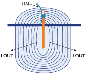
Figure 1: Grounding Rod
A grounding rod, the most efficient and cost-effective connection to earth, is a reinforced bar that is driven deep into the soil. The concrete above the earth acts as a semi-insulator, while concrete underneath the surface acts as a semi-conducting medium. Each footing or foundation has a lower resistance than a single driven rod of the same depth. For structures with a deep foundation, the total resistive connection to the ground is lower than any other non-chemical electrode. The key to an efficient connection is to have either the reinforcing rod or a length of bare copper conductor at the bottom of the concrete.
Grounding rods are typically eight feet long and placed in the soil outside a home or electrical substation to act as grounding electrodes, providing a low-resistance path for fault currents to dissipate into the ground (Figure 1). In the absence of a grounding rod, unconventional methods such as copper water pipes can also serve as grounding connections. In some cases, a grounding wire can be connected to a copper water pipe that extends into the ground as an additional grounding connection for the electrical system.
In general, the grounding rod length requirements are based on the soil conditions, the required grounding resistance, and the local electrical codes. The following table provides a summary of the grounding rod length requirements in some major countries:
| Country | Electrical Code | Requirements |
| United States | National Electrical Code (NEC) | 8 feet minimum, longer may be required |
| Canada | Canadian Electrical Code (CEC) | 10 feet minimum, longer may be required |
| United Kingdom | BS 7671 | 1 meter minimum, longer may be required |
| Australia | AS/NZS 3000 | 1.2 meters minimum, longer may be required |
| India | Indian Standard Code of Practice for Earthing (IS: 3043) | 1.5 meters minimum, longer may be required |
Other methods of grounding include:
- Copper plate grounding involves burying a plate made of galvanized iron or copper vertically at a depth of at least 3m/10ft from ground level. The pit is first filled with charcoal and salt to prevent shock. Charcoal is an excellent conductor, and the addition of salt further increases conductivity. Together, the mix of salt and charcoal prevents electrical accidents by ensuring the leaked current swiftly passes to the earth.
- Pipe grounding involves a galvanized steel pipe of 75mm diameter, 10 feet long, welded with a flange containing six holes for earth wire connection. Soil conditions typically determine the pipe depth (usually 4.75m / 15.5ft).
- Wire grounding involves strip electrodes buried in horizontal holes with a minimum depth of 0.5m. Copper electrodes should have a cross-section of 25mm x 1.6mm, while galvanized iron or steel require a size of 3.0mm.
4. Different Methods of Grounding
Most circuits and electrical systems employ some way of grounding the system neutral at one or more points. These methods can be divided into two general categories: solid grounding and impedance grounding. Impedance grounding can be further divided into several subcategories: reactance grounding, resistance grounding, and ground-fault neutralizer grounding.
- Ungrounded Systems: As the name implies, ungrounded systems are electrical power systems that operate with no connection to the ground, which can make fault detection and location difficult. They have low ground fault currents and a high opportunity cost of faults . Due to associated challenges and risks, commercial and residential applications rarely use ungrounded systems. Grounded systems are more common and provide a simpler approach to fault detection and safety.
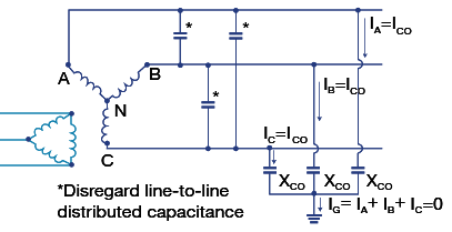
Figure 2: Ungrounded system
- Resistance Grounded Systems: Electrical power systems use resistance grounding to limit fault current through a neutral line (shown in Figure 3). There are two distinct types of resistance grounding systems: high resistance grounding and low resistance grounding.
High Resistance Grounding: High resistance grounding involves connecting an electrical system to the ground with a resistor in series, typically with a resistance value ranging from a few ohms to hundreds of ohms. The purpose of high resistance grounding is to limit fault current to a relatively low value, typically below 10 amperes, minimizing the risk of electrical shock, equipment damage, and fire in the event of a ground fault. High resistance grounding is commonly used in critical applications, such as hospitals, data centers, and process industries, where continuity of operation and personnel safety are paramount. Ground faults can be detected without tripping the entire system and can help avoid service interruptions.
Low Resistance Grounding: Low resistance grounding involves connecting an electrical system to the ground with a grounding conductor that has a very low resistance, typically in the range of 1Ω or less. The primary purpose of low resistance grounding is to quickly detect and clear ground faults, limiting the duration of a fault condition and minimizing equipment damage. Low resistance grounding is commonly used in industrial and commercial applications where the rapid detection and mitigation of ground faults are crucial for minimizing downtime and maintaining the integrity of the electrical distribution system. It is typically accompanied by ground fault protection devices that can quickly trip the system in the event of a fault, thereby facilitating the identification and repair of the fault.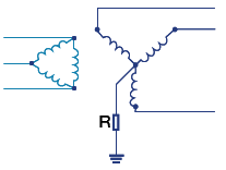
Figure 3: Resistance-grounded system
- Solidly Grounded Systems: As illustrated in Figure 4, a solidly grounded system is a system where the neutral (grounded) conductor of the electrical supply is directly connected to the earth (ground) with minimal resistance. This means that the neutral conductor, which is typically bonded to ground at the service entrance or transformer, provides a low-impedance path to the earth. In the event of a ground fault (short circuit to ground), the low-impedance connection allows a significant current to flow, which is detected by protective devices, such as circuit breakers or fuses. This leads to the rapid disconnection of the faulty circuit.
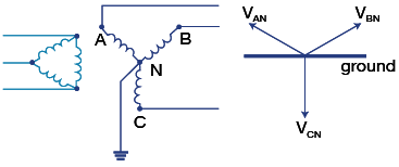
Figure 4: Solidly grounded systems
- Reactance Grounded Systems: A reactance grounded system, also known as an impedance grounded system, is a type of electrical power distribution system in which the neutral conductor is connected to the ground through an intentional impedance, typically a reactor or resistor, as illustrated in Figure 5). This intentional impedance limits the fault current in the event of a ground fault while allowing for some degree of fault detection and localization. This reduced fault current is usually insufficient to operate traditional overcurrent protection devices, such as circuit breakers, which allows the system to remain operational during a single ground fault. To prevent transient overvoltage, reactance grounded systems limit the ground fault current to 25% to 65% of the three-phase short circuit current. Generators use reactance grounding for their neutral conductor, limiting ground fault currents to a value no greater than the generator's three-phase fault current. Reactance grounded systems are often used in critical applications, such as hospitals, data centers, and industrial facilities, where continuous operation is essential. By limiting the impact of a ground fault to a single faulted phase or circuit, these systems help maintain system availability.
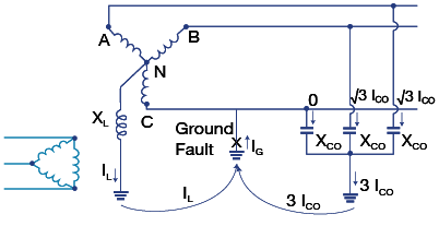
Figure 5: Low reactance grounded system
- Resonant Grounded Systems (Ground Fault Neutralizer): A resonant grounded system utilizes an advanced grounding method to significantly reduce ground fault currents. They employ a tuned reactor, typically consisting of inductors and capacitors, designed to match the system's line-to-ground capacitance, resulting in a reduction of ground fault current magnitude (illustrated in Figure 6). The tuned reactor, also known as a ground fault neutralizer or Peterson coil, is connected between the neutral and the ground of the electrical system.
The key advantage of a resonant grounded system is that the inductive and capacitive components of the currents effectively neutralize each other, preventing in-rush current surges during ground faults. Resonant grounded systems have several benefits, including significant ground fault current reduction, arc suppression, voltage stability, reduced mechanical and thermal stress, and improved system reliability. Resonant grounded systems are typically used in medium and high-voltage electrical networks, particularly in industrial and utility applications, where maintaining continuous operation and minimizing the consequences of ground faults is of utmost importance.

Figure 6: Resonant grounded system
Soil and Other Factors that Affect Grounding Resistance
Grounding resistance is directly affected by the conductivity level of the soil, which in turn determines the ground's resistance. This makes soil conductivity a very important factor in a ground electrode system. The electrical contact area between grounding electrodes and the ground is critical, with larger surface areas resulting in lower resistance. Factors such as conductor characterization, geometrical configuration, soil electrical parameters, number of electrodes, and ground rod diameter also affect grounding resistance.
5. Equipment and Safety Grounding
Equipment grounding is a safety measure to prevent electric shock. It provides a low-resistance path for fault currents to flow into the ground in case of a fault or equipment failure, minimizing the risk of electric shock to individuals who come in contact with the equipment. If the equipment's outer case touches the live wire due to insulation failure, the electric current flows to the ground instead of causing any shock. Electrical outlets use grounding pins to establish equipment grounding.
What is the difference between bonding and grounding?
Bonding and grounding are essential for protecting people and property from electric hazards. Bonding involves connecting non-current-carrying conductive elements like enclosures and structures, while grounding attaches bonded systems to the earth. Electrical grounding, or earthing, connects electrical equipment to the earth to create a conductive path for electricity to flow during lightning strikes, accidental contacts, static charges, and surges. Bonding is necessary for containers that conduct electricity, such as metal or conductive plastics, while grounding may not be necessary for containers made from non-conductive materials like polyethylene plastic or glass.
Grounding systems typically use grounding rods at least 8 feet long and 3/8 inches in diameter, wires, and clamps. Longer or multiple rods are often needed in dry locations where the soil is less conductive and must be spaced at least 6 feet apart. Both bonding and grounding are crucial for ensuring safety and protection in electrical systems.
What are GFCIs?
A Ground Fault Circuit Interrupter (GFCI) is a specialized electrical safety device designed to protect people from electrical shocks, particularly in areas where water and electricity may come into contact. GFCIs are commonly used in residential, commercial, and industrial settings to enhance electrical safety. They are typically 15-30 amperes and measure the current on the supply line, comparing it with the current on the return line. Key features of a GFCI include:
- Ground Fault Detection: GFCIs continuously monitor the balance of electrical current flowing in the hot (live) and neutral conductors of a circuit. If there is a mismatch in the current, even as small as a few milliamperes, it can indicate the presence of a ground fault, which may result from a current leakage to ground due to electrical faults or contact with water.
- Rapid Trip Response: When a GFCI detects a ground fault, it interrupts the circuit within milliseconds, cutting off the electrical power to prevent the risk of electric shock. This rapid response time minimizes the duration of exposure to potentially dangerous electrical conditions.
- Protection from Electric Shock: GFCIs are primarily used to protect people from electric shock hazards. They are commonly installed in areas where water and electricity are in close proximity, such as bathrooms, kitchens, outdoor outlets, and garages.
- Resettable: GFCIs have a reset button that allows users to restore power to the circuit after it has been tripped. This feature makes them convenient for daily use while providing a high level of safety.
- Test Function: GFCIs typically include a test button that allows users to perform routine self-tests. When pressed, the test button simulates a ground fault, causing the GFCI to trip. This function allows users to verify that the GFCI is functioning correctly.
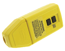
- Multiple Configurations: GFCIs are available in various configurations, including receptacle-type GFCIs that can replace standard electrical outlets, circuit breaker GFCIs installed in electrical panels, and portable GFCI devices used with extension cords.
Hubbell offers standard and AUTOGUARD heavy-duty GFCI receptacles. AUTOGUARD
GFCI receptacles continually test and monitor for “people protection capability” automatically. This patented safety feature includes disconnecting power to the receptacle if critical components are damaged and GFCI protection is lost.
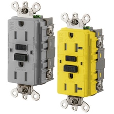
Figure 7: Extra Heavy duty industrial grade GFCI Receptacle. Click here for more GFCI products
6. How to Test an Electrical Ground
Conducting an electrical grounding test is an essential procedure to ensure that the grounding system of a building or electrical equipment is functioning as intended, and ensuring it meets the National Electrical Code (NEC) and other guidelines. Grounding tests are performed to measure the electrical resistance or impedance of the grounding system and verify that it meets safety and performance standards. Grounding systems can deteriorate over time due to corrosion, soil conditions, mechanical damage, and improper installation. Common test methods include the fall of potential test, the clamp-on test, and the three-point test.
Ground Resistance Measurement Using The 3-Point Method
The 3-point method is widely used for measuring the ground resistance of a single grounding electrode. To perform the measurement, drive three test electrodes into the ground in a triangular arrangement around the grounding electrode being tested. Connect the test equipment to these electrodes and inject a known test current and measure the voltage drop. Calculate the ground resistance using Ohm's Law, Rg = V/I.
Fall-Of-Potential Method
The Fall-Of-Potential method is a ground resistance testing technique that measures the energy dissipation of an earth-ground system. It is outlined in the IEEE Std 81 and is commonly used in remote areas with a single earth connection. Place the ground electrode (a test electrode) at a specified distance from the grounding electrode (the grounding system being tested). Connect the test equipment, such as a ground tester or ground resistance meter, to both electrodes. Inject a known current into the ground using the test equipment and measure the voltage drop between the electrodes and calculate the ground resistance using Ohm's law.
Clamp-On Test
This Clamp-on Test is used for measuring ground resistance without disconnecting the ground electrode.
To perform the Clamp-on Test, a clamp-on ground resistance tester is required. Place a clamp-on ground resistance tester around the grounding conductor and inject a test current into the grounding conductor
7. Glossary
- Electrode: a conductor through which electric current enters or leaves a substance, typically through a material where electrochemical reactions occur
- EMI (Electromagnetic Interference): the disruption of normal operation of electronic devices or systems caused by electromagnetic signals in the environment, which can result in undesirable effects such as signal distortion, reduced performance, or complete failure of the affected devices. EMI can arise from various sources, including radio frequency interference, electrical noise, or electromagnetic radiation.
- Floating ground: a condition in which a point in an electrical circuit is not directly connected to the Earth or a common reference point. In such a configuration, the potential of the grounded point is not fixed, and it may vary relative to the Earth or other grounded components in the system.
- Ground Fault: an anomaly that occurs when an unintended electrical connection occurs between a conductor (such as a live wire) and the ground. This can lead to the flow of current through an unintended path, potentially causing electrical hazards and circuit disruptions.
- Opportunity Cost: the value of the next best alternative forgone when a decision is made to allocate resources or time to a particular choice. It represents the potential benefits lost by not choosing the next best alternative.
- Reactance: the opposition that an inductor or capacitor presents to the flow of alternating current (AC), expressed in ohms. It is characterized by its imaginary component in the impedance of a circuit, contributing to the phase shift between voltage and current in AC circuits.
- Reference Point: a designated voltage level used as a baseline for measuring other voltages within the circuit. It serves as a common point of comparison and is often considered the "zero" or neutral potential.
- Resistance: the measure of opposition to the flow of electric current in a conductor. It is typically quantified in ohms and is a fundamental property in electrical circuits influencing the amount of current that can flow through a material for a given voltage.
- Surge: a transient increase in voltage that exceeds the normal operating levels. Surges, often caused by events like lightning strikes or power fluctuations, can potentially damage electronic components and disrupt the normal functioning of electrical systems.
- Star Grounding: a grounding configuration in electrical systems where all grounding conductors are connected to a single central point. This central point serves as a common reference for grounding, minimizing ground loop inductance and reducing the risk of electromagnetic interference in the system.
*Trademark. Hubbell Wiring Device is a trademark of Hubbell Corporation. Other logos, product and/or company names may be trademarks of their respective owners.
For more Hubbell products Shop Now
Test Your Knowledge
Power Skills 7

Complete our Essentials: Power 7 course, rate the document, take the quiz, and leave your feedback to earn this badge.
Are you ready to demonstrate your knowledge about electrical grounding? Then take a quick 10-question multiple choice quiz to see how much you've learned from this module.
To earn the Essentials Power 7 Badge, read through the learning module and attain 100% in the quiz.

