element14 Community
element14 Community
    Register Log In
  • Site
  • Search
  • Log In Register
  • About Us
  • Community Hub
    Community Hub
    • What's New on element14
    • Feedback and Support
    • Benefits of Membership
    • Personal Blogs
    • Members Area
    • Achievement Levels
  • Learn
    Learn
    • Ask an Expert
    • eBooks
    • element14 presents
    • Learning Center
    • Tech Spotlight
    • STEM Academy
    • Webinars, Training and Events
    • Learning Groups
  • Technologies
    Technologies
    • 3D Printing
    • FPGA
    • Industrial Automation
    • Internet of Things
    • Power & Energy
    • Sensors
    • Technology Groups
  • Challenges & Projects
    Challenges & Projects
    • Design Challenges
    • element14 presents Projects
    • Project14
    • Arduino Projects
    • Raspberry Pi Projects
    • Project Groups
  • Products
    Products
    • Arduino
    • Avnet Boards Community
    • Dev Tools
    • Manufacturers
    • Multicomp Pro
    • Product Groups
    • Raspberry Pi
    • RoadTests & Reviews
  • Store
    Store
    • Visit Your Store
    • Choose another store...
      • Europe
      •  Austria (German)
      •  Belgium (Dutch, French)
      •  Bulgaria (Bulgarian)
      •  Czech Republic (Czech)
      •  Denmark (Danish)
      •  Estonia (Estonian)
      •  Finland (Finnish)
      •  France (French)
      •  Germany (German)
      •  Hungary (Hungarian)
      •  Ireland
      •  Israel
      •  Italy (Italian)
      •  Latvia (Latvian)
      •  
      •  Lithuania (Lithuanian)
      •  Netherlands (Dutch)
      •  Norway (Norwegian)
      •  Poland (Polish)
      •  Portugal (Portuguese)
      •  Romania (Romanian)
      •  Russia (Russian)
      •  Slovakia (Slovak)
      •  Slovenia (Slovenian)
      •  Spain (Spanish)
      •  Sweden (Swedish)
      •  Switzerland(German, French)
      •  Turkey (Turkish)
      •  United Kingdom
      • Asia Pacific
      •  Australia
      •  China
      •  Hong Kong
      •  India
      •  Korea (Korean)
      •  Malaysia
      •  New Zealand
      •  Philippines
      •  Singapore
      •  Taiwan
      •  Thailand (Thai)
      • Americas
      •  Brazil (Portuguese)
      •  Canada
      •  Mexico (Spanish)
      •  United States
      Can't find the country/region you're looking for? Visit our export site or find a local distributor.
  • Translate
  • Profile
  • Settings
CodeBug
  • Learn
  • Learning Center
  • STEM Academy
  • CodeBug
  • More
  • Cancel
CodeBug
Forum Heavy Load Switching with CodeBug
  • Blog
  • Forum
  • Documents
  • Events
  • Polls
  • Files
  • Members
  • Mentions
  • Sub-Groups
  • Tags
  • More
  • Cancel
  • New
Join CodeBug to participate - click to join for free!
Actions
  • Share
  • More
  • Cancel
Forum Thread Details
  • State Not Answered
  • Replies 11 replies
  • Subscribers 13 subscribers
  • Views 2328 views
  • Users 0 members are here
  • codebug
  • transistor
  • relay
Related

Heavy Load Switching with CodeBug

spannerspencer
spannerspencer over 9 years ago

Has anyone tried switching slightly heavier loads using the CodeBug's legs, either using a transistor or a relay? I'm working on something that'll need to switch two loads on and off that I'm pretty sure would melt the CodeBug if I did it directly (maybe 1-2 amps each). I'm thinking that something as simple as a transistor, switched from one of the legs, would do the job, but thought I'd ask if anyone's experimented this as yet?

  • Sign in to reply
  • Cancel

Top Replies

  • shabaz
    shabaz over 9 years ago +4
    The 'GPIO Explained' schematic with the transistor and relay should work too. (For some reason the editor is mangling the URL - will raise a feedback & support request. Circuit is below): ( Finder 32.21…
  • michaelkellett
    michaelkellett over 9 years ago in reply to jc2048 +2
    Oh John, you're such an optimist I read the same data sheet and come away with 40 - 50 mOhms (40 @ 2.5V gate drive + about 30% for being hot). But still good for 3A (just about at ambient = 25) MK
  • mcb1
    mcb1 over 9 years ago +1
    At the risk of a certain intervention ... http://www.itead.cc/electronic-brick-5v-relay.html?___SID=U http://www.itead.cc/2-channels-5v-relay-module.html?___SID=U If you check the wiki they include a transistor…
  • balearicdynamics
    0 balearicdynamics over 9 years ago

    Not yet, but I'm almost sure it works. I have used a PN2222 to manage high load with a 3V on a PI so why not ?

    • Cancel
    • Vote Up 0 Vote Down
    • Sign in to reply
    • Verify Answer
    • Cancel
  • mcb1
    0 mcb1 over 9 years ago

    At the risk of a certain intervention ...

    http://www.itead.cc/electronic-brick-5v-relay.html?___SID=U

    http://www.itead.cc/2-channels-5v-relay-module.html?___SID=U


    If you check the wiki they include a transistor driving the relay.


    The other thought is Terry King has optocoupled units.

    http://yourduino.com/sunshop2/index.php?l=product_detail&p=218


    Mark

    • Cancel
    • Vote Up +1 Vote Down
    • Sign in to reply
    • Verify Answer
    • Cancel
  • shabaz
    0 shabaz over 9 years ago

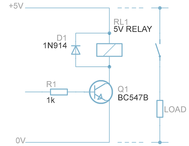
    The 'GPIO Explained' schematic with the transistor and relay should work too.

    (For some reason the editor is mangling the URL - will raise a feedback & support request. Circuit is below):

    image


    (Finder 32.21.7.005.2000Finder 32.21.7.005.2000 is a convenient relay for up to 6A, fits stripboard nicely).

    Or a MOSFET based circuit, but I left them out of GPIO Explained due to opportunities to go wrong if people attempt to use alternatives!),

    • Cancel
    • Vote Up +4 Vote Down
    • Sign in to reply
    • Verify Answer
    • Cancel
  • jc2048
    0 jc2048 over 9 years ago

    A MOSFET like this would do you (assuming that your load is operating from a voltage less than 20V)


    http://uk.farnell.com/taiwan-semiconductor/tsm2312cx/mosfet-n-ch-20v-4-9a-sot23/dp/1864587


    The Vbe threshold is low enough that the 3V CodeBug outputs will switch it. The on resistance is only 27mOhms, so even at 3A it only has to dissipate a quarter of a watt (0.243W) which the package alone should manage.


    Connect the gate to the CodeBug output, the source to GND, and the drain to your load (with the other side of the load connected to the supply you're using). Remember to connect the ground of the CodeBug and the ground of the load power supply together.


    If the load is inductive (coil of some sort) include a catching diode as per the transistor circuit in shabaz's post.


    Observe static precautions handling the transistor before you get it wired in the circuit.


    If you want to prevent it turning on and off  before the CodeBug initialises its output pin ("flapping around" to use the technical term), include a resistor from the gate down to ground to keep the MOSFET turned off until it is actually being properly driven by the output.


    If you decide to take this approach, let us all know how you get on.

    • Cancel
    • Vote Up +1 Vote Down
    • Sign in to reply
    • Verify Answer
    • Cancel
  • spannerspencer
    0 spannerspencer over 9 years ago in reply to jc2048

    Ah, nice! I was just this moment looking at an AOT460 MOSFET for the same purpose, Jon -- but the one you suggested looks preferable (cheaper, too!). Excellent suggestion, and thanks for the setup description.

    • Cancel
    • Vote Up +1 Vote Down
    • Sign in to reply
    • Verify Answer
    • Cancel
  • spannerspencer
    0 spannerspencer over 9 years ago in reply to shabaz

    Excellent suggestion, Shabaz, and I'm now wondering whether to go with Jon's MOSFET option, or whether to get a double pole relay and switch both loads from just one of the CodeBug's legs. Although I may need to control them separately... I'll have to think about that some more image


    Either way, always appreciate the ideas from all your guys!

    • Cancel
    • Vote Up +1 Vote Down
    • Sign in to reply
    • Verify Answer
    • Cancel
  • shabaz
    0 shabaz over 9 years ago in reply to spannerspencer

    Hi Spanner,


    Personally I'd go with Jon's suggestion for my own boards, only caveat is that it is a surface mount device which not everyone is comfortable with. If you're using a relay, then you may as well use the NPN method, since it doesn't care what specific NPN transistor you use.

    But yes, many ways to swing a cat : )

    • Cancel
    • Vote Up +1 Vote Down
    • Sign in to reply
    • Verify Answer
    • Cancel
  • jc2048
    0 jc2048 over 9 years ago in reply to shabaz

    Absolutely. And there may be real advantages to having the isolation that the relay gives; without knowing a bit more about what "Spanner Spencer" is trying to do it's difficult to say.


    The bipolar transistor is much more robust handling-wise, too, particularly if poeple aren't used to electronics and don't understand about the possibility of static damage.


    Soldering an SOT23 is quite easy, though. They're probably the easiest SMD parts to prototype with (at least I can see the things, which isn't the case with some of the surface mount resistors you can get now).

    • Cancel
    • Vote Up +1 Vote Down
    • Sign in to reply
    • Verify Answer
    • Cancel
  • michaelkellett
    0 michaelkellett over 9 years ago in reply to jc2048

    Oh John, you're such an optimist image


    I read the same data sheet and come away with 40 - 50 mOhms (40 @ 2.5V gate drive + about 30% for being hot).


    But still good for 3A (just about at ambient = 25)


    MK

    • Cancel
    • Vote Up +2 Vote Down
    • Sign in to reply
    • Verify Answer
    • Cancel
  • jc2048
    0 jc2048 over 9 years ago in reply to michaelkellett

    Mea culpa!


    It was staring me in the face right at the top, too. But he/she did only ask for 1 to 2A, and the typical rds-on would be a bit better, and I presume this is experimenting and hacking rather than straight product design, so I think we'd get away with it. But you're right, it doesn't set a particularly good example.


    Curiously, by nature, I'm a right old pessimist.


    BTW Your post really confused me at first (calling me John) because when I'm logged in I see my real name (Jonathan) above my posts and I presumed that was what everyone else saw too. What an odd system.

    • Cancel
    • Vote Up 0 Vote Down
    • Sign in to reply
    • Verify Answer
    • Cancel
>
element14 Community

element14 is the first online community specifically for engineers. Connect with your peers and get expert answers to your questions.

  • Members
  • Learn
  • Technologies
  • Challenges & Projects
  • Products
  • Store
  • About Us
  • Feedback & Support
  • FAQs
  • Terms of Use
  • Privacy Policy
  • Legal and Copyright Notices
  • Sitemap
  • Cookies

An Avnet Company © 2025 Premier Farnell Limited. All Rights Reserved.

Premier Farnell Ltd, registered in England and Wales (no 00876412), registered office: Farnell House, Forge Lane, Leeds LS12 2NE.

ICP 备案号 10220084.

Follow element14

  • X
  • Facebook
  • linkedin
  • YouTube