I have a strange issue with the micro:bit that I have no idea by what it can depends. Maybe also a behavioural detail I have not considered and I am expecting something that it is normal does not happens.
The scenario
For more detail on how the project is designed take a look to the blog posts on Tempus fugit...
Tempus Fugit... Part 1: 1978 a.d. project intro
Tempus Fugit... Part 2: 2018 a.d. the components and the logic of the project
Tempus Fugit... Part 3: micro:bit Interfacing 5V Logic the first issue: interfacing 3.3 logic signals from micro:bit to 5V logic on IC. Tested and solved
Tempus Fugit... Part 4: micro:bit 5V SPI adopting the solution discussed in the previous blog post to my use case: 7-segments LED controller via SPI protocol.
The problem
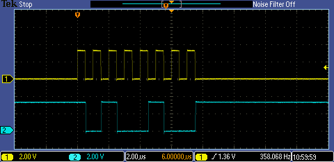
Hardware seems working properly; with simple programs to control the pins involved by the SPI protocol (13, 14, 15 on the micro:bit) and testing with the oscilloscope bon both sides 3.3 V (output connector from the micro:bit) and 5V (input connection to the IC) these works perfectly and there are no problems. Then, I tried to implement in Python using MU the SPI protocol and on the same pins controlling with the oscilloscope nothing happens. To do this I have used the Python library to control the specific IC but none at all. I am not interested in this moment to see the display working. What I just need to understand is what can be the issue that is blocking the SPI protocol to work correctly, also when the test program runs on on the micro:bit without the controlled circuit connected to avoid interferences. The same behaviour happens on a second micro:bit board, while the digital output setting of the pins with the test program continue working; I can suppose that there is not any hardware problem.
Any suggestion and idea is more than welcome 
Enrico