I'm looking for some help with resolving a noise and what I believe is stability problem of a -5V LDO regulator. Here is the circuit:

and in case it's useful, the relevant part of the PCB:

The circuit section I'm having difficulty with is the top right (yellow ICs). I have a 285Ohm resistor soldered across terminals of TP9 and it draws 17.5mA. R22 and C34 are not populated.
The TC7662TC7662 DC-DC charge pump, is fed from a regulated 12V and outputs -11.8V to feed into a -5V LDO regulatorMC7905CDMC7905CD which is outputting -5.011V.
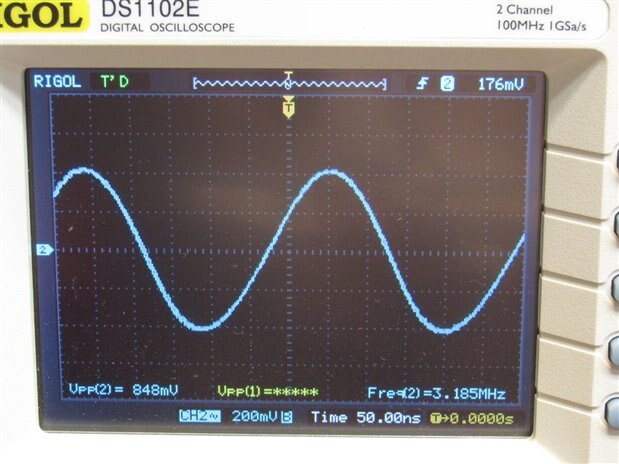
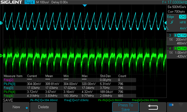
When I take measurements (AC coupled, BW 20MHz, 1xprobe with the pigtail rather than flying lead) of the charge pump output (at TP12) and -5V output (at TP9) I get:
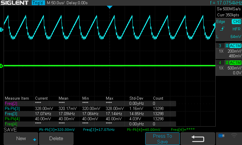
CH3: Charge Pump output with HF reject on (matches what is expected in the datasheet). I was expecting that the frequency of the output would be 35kHZ due to way I have pins 1 and 8 connected together.

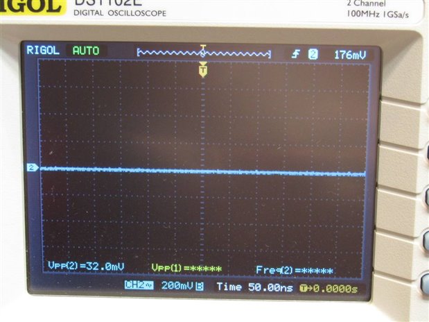
CH4: -5 LDO output with LF reject on.
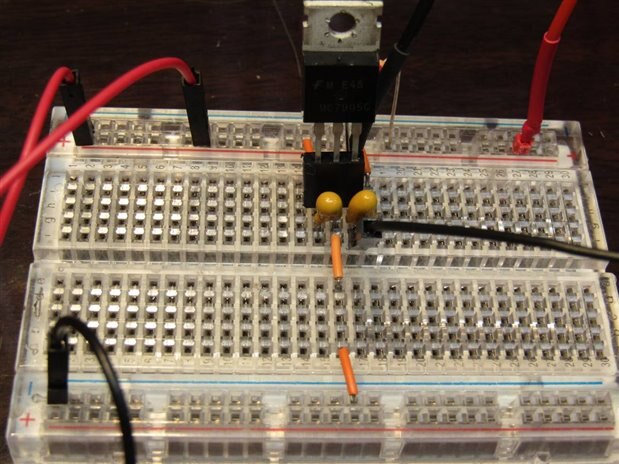
I think the LDO output looks like it is oscillating. Looking at the circuit the input capacitor, C18, is too small and should be a 0.33uF tantalum for stability, according to the datasheet but I have used a 0.33 ceramic capacitor as I don't have any useable tantalums and my thinking was the ceramic should have a low ESR. I've actually tried with 22uF and then a 68uF electrolytic capacitors, in parallel, but both have zero effect on the LDO output which remains steadfastly at 1.32V. I've tried the circuit on a breadboard but unfortunately I only have a TI LM7905 - this seems to work ok even with the original capacitor value and doesn't oscillate. I think the TI part behaves differently so it's not a great comparison. Its output is slightly improved with a 22uF input capacitor.
I really thought that adding an electrolytic capacitor at the input would help (the ESR of the 22uF was around 2.2Ohm) but it makes no difference at all. I'm out of ideas short of "it really needs a tantalum capacitor on the input", so I'm putting this out there to see if anyone can give me pointers or things to try.