element14 Community
element14 Community
    Register Log In
  • Site
  • Search
  • Log In Register
  • About Us
  • Community Hub
    Community Hub
    • What's New on element14
    • Feedback and Support
    • Benefits of Membership
    • Personal Blogs
    • Members Area
    • Achievement Levels
  • Learn
    Learn
    • Ask an Expert
    • eBooks
    • element14 presents
    • Learning Center
    • Tech Spotlight
    • STEM Academy
    • Webinars, Training and Events
    • Learning Groups
  • Technologies
    Technologies
    • 3D Printing
    • FPGA
    • Industrial Automation
    • Internet of Things
    • Power & Energy
    • Sensors
    • Technology Groups
  • Challenges & Projects
    Challenges & Projects
    • Design Challenges
    • element14 presents Projects
    • Project14
    • Arduino Projects
    • Raspberry Pi Projects
    • Project Groups
  • Products
    Products
    • Arduino
    • Avnet Boards Community
    • Dev Tools
    • Manufacturers
    • Multicomp Pro
    • Product Groups
    • Raspberry Pi
    • RoadTests & Reviews
  • Store
    Store
    • Visit Your Store
    • Choose another store...
      • Europe
      •  Austria (German)
      •  Belgium (Dutch, French)
      •  Bulgaria (Bulgarian)
      •  Czech Republic (Czech)
      •  Denmark (Danish)
      •  Estonia (Estonian)
      •  Finland (Finnish)
      •  France (French)
      •  Germany (German)
      •  Hungary (Hungarian)
      •  Ireland
      •  Israel
      •  Italy (Italian)
      •  Latvia (Latvian)
      •  
      •  Lithuania (Lithuanian)
      •  Netherlands (Dutch)
      •  Norway (Norwegian)
      •  Poland (Polish)
      •  Portugal (Portuguese)
      •  Romania (Romanian)
      •  Russia (Russian)
      •  Slovakia (Slovak)
      •  Slovenia (Slovenian)
      •  Spain (Spanish)
      •  Sweden (Swedish)
      •  Switzerland(German, French)
      •  Turkey (Turkish)
      •  United Kingdom
      • Asia Pacific
      •  Australia
      •  China
      •  Hong Kong
      •  India
      •  Korea (Korean)
      •  Malaysia
      •  New Zealand
      •  Philippines
      •  Singapore
      •  Taiwan
      •  Thailand (Thai)
      • Americas
      •  Brazil (Portuguese)
      •  Canada
      •  Mexico (Spanish)
      •  United States
      Can't find the country/region you're looking for? Visit our export site or find a local distributor.
  • Translate
  • Profile
  • Settings
Community Hub
Community Hub
Member's Forum Bistable/latching solenoid valve control circuit. Please help!
  • Blog
  • Forum
  • Documents
  • Quiz
  • Events
  • Leaderboard
  • Polls
  • Files
  • Members
  • Mentions
  • Sub-Groups
  • Tags
  • More
  • Cancel
  • New
Join Community Hub to participate - click to join for free!
Actions
  • Share
  • More
  • Cancel
Forum Thread Details
  • State Suggested Answer
  • Replies 21 replies
  • Answers 17 answers
  • Subscribers 536 subscribers
  • Views 6521 views
  • Users 0 members are here
  • change polarity
  • solenoid valve
Related

Bistable/latching solenoid valve control circuit. Please help!

sim.parkin
sim.parkin over 7 years ago

Hi there.


This is my first time posting and it's about my first electronics project since school image. So no need to say that i apologise if what I am asking is very simple but still I hope some one can help me.


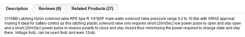
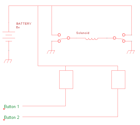
So here's the situ... I want to be able to remotely switch a hose pipe on, but the thing is, the system is fixed into my vehicle so the whole thing has to be portable and run off batteries. I have a remote switch that at the press of a button (on the remote) can momentarily (or it can be set to self lock also) connect the battery to the solenoid valve and switch it on but the valve needs the polarity to be reversed and pulsed to switch it off again. For love nor money can I figure out a way of doing this? My head is in a whirl from all the h-bridge... dpdt relays... flipflops... etc.... every time I research something it seems I need something else to make it work. (if that makes sense) I am lost.


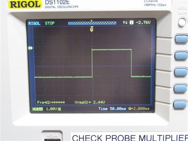
In short what I want to do is: Press the button on the remote control once and it turn the water flow on, and press it again and the water turn off. Basically its a momentary push button input that alternates between a +6v output and a -6v output. If that is possible.


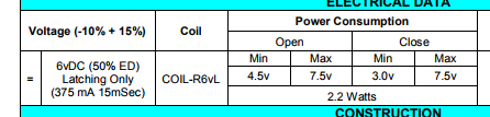
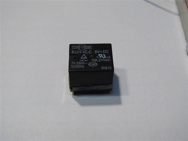
I want to use this latching type relay because you can get low power ones of this type, but they also save battery power by only requiring a pulse of electricity to change state, rather than energising a coil for longer periods of time. Oh and I also want to avoid using microcontrollers if possible because I can't code.


Really hope someone out there can help. I also hope I remembered everything, if I missed something just let me know.


Thanks for reading.


Simon.


p.s. I found one other post like this with a guy with my exact problem but he gave up and used a non-latching type. image

  • Sign in to reply
  • Cancel

Top Replies

  • jw0752
    jw0752 over 7 years ago in reply to sim.parkin +4 suggested
    Hi Simon, The additional information was helpful and from this information in the data sheet: I have a little more confidence that my circuit can be made to work. Keep in mind you may have to experiment…
  • sim.parkin
    sim.parkin over 7 years ago +3 suggested
    Hi there Guys. Wowsers!! That was both quick and excellent!! Thanks so much for your help with this! Sorry for not being able to reply until now... life . I knew it was possible but couldn't get there…
  • jw0752
    jw0752 over 7 years ago +2 suggested
    Hi Simon, I may have a possible solution for you. This is a bistable or Flip flop that I was playing with the other day. This one is triggered by sound but it could just as easily be triggered with a momentary…
  • jw0752
    0 jw0752 over 7 years ago in reply to sim.parkin

    Hi Simon,

    The additional information was helpful and from this information in the data sheet:


    image


    I have a little more confidence that my circuit can be made to work. Keep in mind you may have to experiment with the size of C3 and C4 as well as the value of R10 and R11. According to the Data sheet we need 375 mA for 15 mSec to actuate the solenoid.

    Here is the schematic. I am not an engineer and sometimes I don't get things right. Fortunately there are some really sharp guys here that look over my shoulder and help with needed corrections.


    image

    Click on the schematic to get an enlarged view. I have also attempted to attach a bit map file of the schematic so hopefully you can print a copy.


    Please continue to post your progress so we can see how your project turns out.


    John

    • Cancel
    • Vote Up +4 Vote Down
    • Sign in to reply
    • Verify Answer
    • Reject Answer
    • Cancel
  • sim.parkin
    0 sim.parkin over 7 years ago in reply to jw0752

    Hi John.


    Thanks so much for the schematic. It is very interesting. I saw this type of flip flop in my research... its the inclusion of the mosfets i had no idea about. Good one!! image image

    I will have to breadboard this out when the valve arrives and fine tune as you instruct. Cant wait. image

    After shopping around, I found this solenoid valve and bought it but it needs a longer pulse I notice. https://www.ebay.co.uk/itm/DC6V-1-2-Electric-Solenoid-Valve-Water-Fuel-Electromagnetic-Valve-White/122324613817?ssPageNa…  Can you help me understand how to alter the circuit to its spec? I think I have to change the capacitors but possibly also something else? the ad doesn't give a current draw but am i right in saying we can get this from the coil resistance in ohms that is given? 6v / 9Ω is 667ma is that right? Possibly missing something.


    Of course I will stay in touch and let you know how it all goes. Just have to wait for all the parts now. image


    Kindest regards.


    Simon.

    • Cancel
    • Vote Up +1 Vote Down
    • Sign in to reply
    • Verify Answer
    • Cancel
  • jw0752
    0 jw0752 over 7 years ago

    Hi Simon,

    I was back in the shop playing with this idea. I have changed the capacitors to 1000 uF and I have changed  R10 and R11 to 390 ohms. I hooked up a small 6 volt DC relay with a 100 ohm coil to see if it could be actuated. Here is the relay:


    image


    I put my analog ohmmeter across the NO contacts in parallel with my scope probes. This should give me about 3 volts on the scope when the contacts are open and zero volts when they close. Here is the scope image of the relays contacts.


    image


    As you can see the pulse was strong enough to close the relay contacts for 200 mSec. This relay is fairly easy to actuate so I am not sure that it is a good model for your solenoid. You will have to do some experimentation. I am calculating that we had a peak of about 70 mA to the relay coil and dropping from there as the capacitor charged.


    John

    • Cancel
    • Vote Up +1 Vote Down
    • Sign in to reply
    • Verify Answer
    • Reject Answer
    • Cancel
  • sim.parkin
    0 sim.parkin over 7 years ago in reply to jw0752

    Hi John.


    This is very positive image. I am looking forward to having a tinker myself when the parts all arrive.


    Over and out for now.


    Simon.

    • Cancel
    • Vote Up +1 Vote Down
    • Sign in to reply
    • Verify Answer
    • Cancel
  • mcb1
    0 mcb1 over 7 years ago in reply to sim.parkin

    sim.parkin

    As I suspected this uses the water to provide the latching effect.

    image

    jw0752 cct will provide the required pulse but you need to reverse the voltage onto the solenoid.


    IMO the best idea is to use an HBridge.

    The L298N series are often used to control motors, but the solenoid coil is basically the same thing.

    Arduino DC Motor Control Tutorial - L298N | PWM | H-Bridge - HowToMechatronics


    Motor2.png


    For this application, the solenoid would be connected across J2 and you would tie ENA high, and then make IN1 High and IN2 low (or hold it low with a resistor), and it will operate one way, Reversing the IN1,2 will make it go the other way.

    Most remote controls provide a pulse out, and you simply connect one remote output to IN1 and the other to IN2. (They can be either High or Low, it's when they are different the motor/solenoid is powered.)


    The L298N boards are available for a few dollars on the Asian websites.


    The other method involves a DPDT relay to reverse the connection to the solenoid, and a pulse of the power.


    Mark

    • Cancel
    • Vote Up +2 Vote Down
    • Sign in to reply
    • Verify Answer
    • Reject Answer
    • Cancel
  • jw0752
    0 jw0752 over 7 years ago in reply to mcb1

    Hi Mark,


    The circuit that I made does reverse the polarity with each trigger. It wasn't clear in your post if you caught this.


    I suspect that the solenoid has a plunger that is a magnet and hence the need to reverse the polarity to throw it in to the opposite state.


    John

    • Cancel
    • Vote Up 0 Vote Down
    • Sign in to reply
    • Verify Answer
    • Reject Answer
    • Cancel
  • mcb1
    0 mcb1 over 7 years ago in reply to sim.parkin
    6v / 9Ω is 667ma is that right?

    Correct.

    The reality is that an inductive coil (motor/solenoid) will draw more as it gets powered up due to the magnetic effect trying to resist change.

    For smaller inductances 1.5 to 2 times is a general figure, but that is only for a short time, while the constant drain is as you calculated above ... not that they are designed to be on all time.


    In reality the length of time you are going to apply power onto the solenoid is nothing.

    The standby power for the receiver is likely to be greater over 24hrs than the time to energise/de-energise the solenoid.


    Mark

    • Cancel
    • Vote Up 0 Vote Down
    • Sign in to reply
    • Verify Answer
    • Reject Answer
    • Cancel
  • sim.parkin
    0 sim.parkin over 7 years ago in reply to mcb1

    Hi Mark.


    Thank you very much for your input there. I did quite a bit of research on h bridges. I have been thinking about your solution and it appeals because i can just buy a board 'off the shelf' so to speak. But if i have a two button remote control can't i just hook one relay up to the battery and hook the other one in the opposite polarity? I think this is what you mention at the end of your post. I cant really see the advantage of using the h bridge because it has to have two inputs anyway, but if I missed something (quite probable) please let me know.


    Thanks again for your help and advise! image


    Best regards.


    Simon.

    • Cancel
    • Vote Up +1 Vote Down
    • Sign in to reply
    • Verify Answer
    • Cancel
  • mcb1
    0 mcb1 over 7 years ago in reply to sim.parkin

    can't i just hook one relay up to the battery and hook the other one in the opposite polarity?

    Two SPDT relays driven from two buttons would work just as well.

    You can purchase dual relays from many asian suppliers, and most are 5v but will handle 6v for a short period.


    image

    Most of the relays are set for ground to operate (Active LOW), but some allow either.


    You will need to check how long the remote receiver provides the pulse for.

    A simple LED (and resistor) will tell you, and if it's too long then it might still require some magic electronics.


    Mark

    • Cancel
    • Vote Up +1 Vote Down
    • Sign in to reply
    • Verify Answer
    • Reject Answer
    • Cancel
  • yoyozhou
    0 yoyozhou over 4 years ago in reply to jw0752

    Hi John ,


    You are very kind .Your video looks good .


    We are a professional manufacture of latching water solenoid valve ,and our water solenoid valves commonly used in intelligent sanitary ware ,intelligent water irrigation timer etc.


    If any need i will be so glad to work for you ,thanks


    yoyo@hbcsn.com


    image


    Best Regards

    Yoyo

    • Cancel
    • Vote Up +1 Vote Down
    • Sign in to reply
    • Verify Answer
    • Reject Answer
    • Cancel
<>
element14 Community

element14 is the first online community specifically for engineers. Connect with your peers and get expert answers to your questions.

  • Members
  • Learn
  • Technologies
  • Challenges & Projects
  • Products
  • Store
  • About Us
  • Feedback & Support
  • FAQs
  • Terms of Use
  • Privacy Policy
  • Legal and Copyright Notices
  • Sitemap
  • Cookies

An Avnet Company © 2025 Premier Farnell Limited. All Rights Reserved.

Premier Farnell Ltd, registered in England and Wales (no 00876412), registered office: Farnell House, Forge Lane, Leeds LS12 2NE.

ICP 备案号 10220084.

Follow element14

  • X
  • Facebook
  • linkedin
  • YouTube