element14 Community
element14 Community
    Register Log In
  • Site
  • Search
  • Log In Register
  • Community Hub
    Community Hub
    • What's New on element14
    • Feedback and Support
    • Benefits of Membership
    • Personal Blogs
    • Members Area
    • Achievement Levels
  • Learn
    Learn
    • Ask an Expert
    • eBooks
    • element14 presents
    • Learning Center
    • Tech Spotlight
    • STEM Academy
    • Webinars, Training and Events
    • Learning Groups
  • Technologies
    Technologies
    • 3D Printing
    • FPGA
    • Industrial Automation
    • Internet of Things
    • Power & Energy
    • Sensors
    • Technology Groups
  • Challenges & Projects
    Challenges & Projects
    • Design Challenges
    • element14 presents Projects
    • Project14
    • Arduino Projects
    • Raspberry Pi Projects
    • Project Groups
  • Products
    Products
    • Arduino
    • Avnet Boards Community
    • Dev Tools
    • Manufacturers
    • Multicomp Pro
    • Product Groups
    • Raspberry Pi
    • RoadTests & Reviews
  • Store
    Store
    • Visit Your Store
    • Choose another store...
      • Europe
      •  Austria (German)
      •  Belgium (Dutch, French)
      •  Bulgaria (Bulgarian)
      •  Czech Republic (Czech)
      •  Denmark (Danish)
      •  Estonia (Estonian)
      •  Finland (Finnish)
      •  France (French)
      •  Germany (German)
      •  Hungary (Hungarian)
      •  Ireland
      •  Israel
      •  Italy (Italian)
      •  Latvia (Latvian)
      •  
      •  Lithuania (Lithuanian)
      •  Netherlands (Dutch)
      •  Norway (Norwegian)
      •  Poland (Polish)
      •  Portugal (Portuguese)
      •  Romania (Romanian)
      •  Russia (Russian)
      •  Slovakia (Slovak)
      •  Slovenia (Slovenian)
      •  Spain (Spanish)
      •  Sweden (Swedish)
      •  Switzerland(German, French)
      •  Turkey (Turkish)
      •  United Kingdom
      • Asia Pacific
      •  Australia
      •  China
      •  Hong Kong
      •  India
      •  Korea (Korean)
      •  Malaysia
      •  New Zealand
      •  Philippines
      •  Singapore
      •  Taiwan
      •  Thailand (Thai)
      • Americas
      •  Brazil (Portuguese)
      •  Canada
      •  Mexico (Spanish)
      •  United States
      Can't find the country/region you're looking for? Visit our export site or find a local distributor.
  • Translate
  • Profile
  • Settings
Community Hub
Community Hub
Member's Forum Trailer Lights Logic
  • Blog
  • Forum
  • Documents
  • Quiz
  • Events
  • Leaderboard
  • Polls
  • Files
  • Members
  • Mentions
  • Sub-Groups
  • Tags
  • More
  • Cancel
  • New
Join Community Hub to participate - click to join for free!
Actions
  • Share
  • More
  • Cancel
Forum Thread Details
  • Replies 16 replies
  • Subscribers 508 subscribers
  • Views 1019 views
  • Users 0 members are here
  • logic
  • signal
  • light
  • brake
  • towing
  • trailer
Related

Trailer Lights Logic

ntewinkel
ntewinkel over 8 years ago

Hi all,


Remember this discussion (https://www.element14.com/community/message/201594/l/re-using-12v-at-base-of-transistor) a while back?


That's when I started a project involving a little travel trailer and trying to use a basic 4-wire wiring connection to properly light up separate brake and signal lights.


To sum up: the 4 wire connection from the car consists of: Ground, Marker lights (for night use), Left, and Right.

What that really means is that the brake and signal lights are combined in the 2 wires for left and right. Usually trailers just have a red light on the left and a red light on the right, and they do their thing.


But I bought fancy LED lights that separate out the brakes and the signal lights. Which left me trying to figure out if it was possible to do some logic to properly handle the brake and signal lights to their full potential... without rewiring the harness on the car!


I think I've found a way to do this using logic chips. And from what I can tell, the 4000 series chips will handle up to 18 volts, which is plenty to handle whatever the tow vehicle will throw my way.


I played around with it on this website I found (Simulator.io), and it seems to work like I want it to.

http://simulator.io/board/qQCIfvpreQ/3

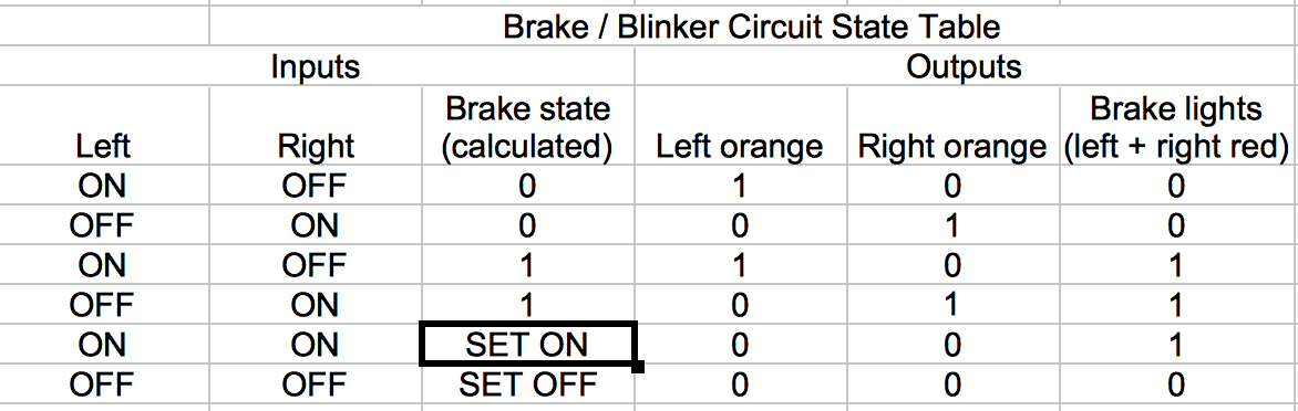
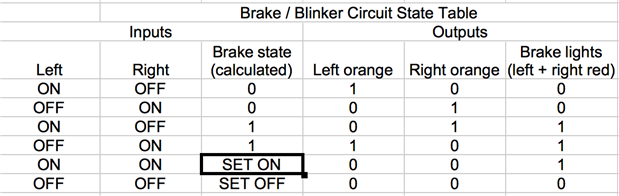
1. If either the left or right wire is on, that orange indicator will go on, giving properly blinking

2. if both wires are on, the red brake lights go on, giving proper brake light function

3. if the brakes go on, the brake lights will remain on as long as there is power to the system (ie, at least one of the left or right wires has power)

4. if the brakes are on and one of the left or right wire goes off, then that indicator light goes one - essentially, the one side that's blinking will end up blinking but in reverse to how the car is blinking.


image


If you follow that URL above, you can play with the circuit - clicking on the "0" box beside the "Left" and "Right" inputs simulate the wire coming from the car.


I was going to test this using the 7400 series chips I have (using 5 volts and LEDs), but sadly I don't have any OR chips! (I'll have to fix that soon!). And making them from NAND chips looks to be very painful.


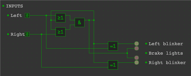
Here is my logic (edit: I had the wrong picture here earlier)

image

Special thanks goes to Michael Kellett michaelkellett for the idea of latching the brake lights ON and keeping it on until both wires are off.

And another special thanks goes to Douglas Wong dougw for the idea of putting together a logic truth table - that helped me get things straight in my mind, and gave me the idea to try using logic chips.


Anyway, what do you all think? Am I overlooking any potential problems?


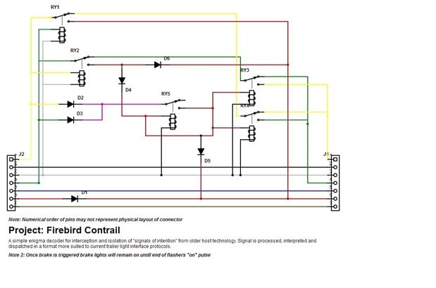
ps, I think I also figured out a way to achieve this using just relays, but I figured solid state would be smaller and easier.


Thanks,

-Nico


edit: Note mostly to self: I have updated the trailer lights logic to now also reset when both blinker lights are off: https://simulator.io/board/qQCIfvpreQ/4

This allows the circuit to retain power and still function properly. The previous logic required power to be shut down in order to reset. The new logic allows battery or super-cap backup to keep it on.

  • Sign in to reply
  • Cancel

Top Replies

  • michaelkellett
    michaelkellett over 8 years ago +2
    Hello Nico, Generally when designing electronics for automotive use you should go for the following rough electrical spec: "12V" supply, 5 - 28V continuous, -12V continuous, system should work correctly…
  • michaelkellett
    michaelkellett over 8 years ago in reply to ntewinkel +1
    There are automotive rated voltage regulators you could use to get the 5V (don't use a 7805) but in your case I would go for 4000 or 74HC series logic (low current) and a simple series R shunt zener regulator…
  • michaelkellett
    michaelkellett over 8 years ago in reply to michaelkellett +1
    Hello Nico, Just found this useful paper from TI re. automotive power supplies. Lots of useful background as well as specifics for a high performance (and high cost) design. http://www.ti.com/general/docs…
  • michaelkellett
    michaelkellett over 8 years ago

    Hello Nico,


    Generally when designing electronics for automotive use you should go for the following rough electrical spec:


    "12V" supply, 5 - 28V continuous, -12V continuous, system should work correctly 10V - 16V or more. 80V for 500mS


    Any input or port should stand spikes of perhaps 250V for 1us and static discharge, human body model, of at least 8kv.


    All this means is that your CMOS logic should be protected by a series resistor and shunt capacitor//zener diode on its power supply and that each logic input should be connected to a series R and a pair of diodes (one to ground and one to protected supply).


    You may need to filter the inputs to stop noise spikes form causing problems - which would mean adding shunt capacitors to the inputs (on the circuit side of the series R).


    I don't really like using feedback around gates but it may work OK - you'll need to test it. 4000 series logic is fine if you protect it - nice and slow.


    MK

    • Cancel
    • Vote Up +2 Vote Down
    • Sign in to reply
    • Cancel
  • ntewinkel
    ntewinkel over 8 years ago in reply to michaelkellett

    "12V" supply, 5 - 28V continuous, -12V continuous, system should work correctly 10V - 16V or more. 80V for 500mS

    Ooh that does sound messy image


    The other way I was thinking of doing it was to convert the inputs to 5v using 2 LM7805 regulators (one for each input), and using 7400 series logic. The thinking was that the regulators will clean up the supply a bit. Looks like I'd still need the capacitor and zener diode to deal with spikes though.


    And, of course, in either case the outputs would be using transistors to switch the lights.


    Thanks for making me aware of exactly how messy the power can be. I was thinking it was give or take a few volts!


    Thanks,

    -Nico

    • Cancel
    • Vote Up 0 Vote Down
    • Sign in to reply
    • Cancel
  • michaelkellett
    michaelkellett over 8 years ago in reply to ntewinkel

    There are automotive rated voltage regulators you could use to get the 5V (don't use a 7805) but in your case I would go for 4000 or 74HC series logic (low current) and  a simple series R shunt zener regulator. (Make sure it isn't permanently connected to your battery.) This simple arrangement gives you power supply protection against all the expected horrors.


    The logic inputs need protection as well but you can use cheap diodes and series resistors. In the past I've used input transistors to buffer inputs, you still need the series R (and a collector R) but only one shunt diode. You get better defined switching thresholds with the transistors.


    Watch out for the base current if you use transistors for the output switches - MOSFETs might be better or possibly a darlington like BSP52 (Farnell 1698153).


    MK

    • Cancel
    • Vote Up +1 Vote Down
    • Sign in to reply
    • Cancel
  • michaelkellett
    michaelkellett over 8 years ago in reply to michaelkellett

    Hello Nico,


    Just found this useful paper from TI re. automotive power supplies. Lots of useful background as well as specifics for a high performance (and high cost) design.


    http://www.ti.com/general/docs/lit/getliterature.tsp?baseLiteratureNumber=tiduc41&fileType=pdf


    MK

    • Cancel
    • Vote Up +1 Vote Down
    • Sign in to reply
    • Cancel
  • mcb1
    mcb1 over 8 years ago

    Somehow I missed this part of the discussion.


    I was due to have a similar issue, where here in NZ we use the seperate indicator lights, but american cars combine everything.


    I spent some considerable time trying to work it out, and in the end opted to just buy one of these.

    https://www.amazon.com/Tow-Ready-118158-Taillight-Converter/dp/B001GKQZQG


    I haven't tried it ... that car got killed before the tow bar went on, and I'm still deciding whether to add one to the replacement.


    Mark

    • Cancel
    • Vote Up +1 Vote Down
    • Sign in to reply
    • Cancel
  • ntewinkel
    ntewinkel over 8 years ago in reply to mcb1

    I might go that route if my project doesn't succeed.


    It's $40 CAD on the Canadian Amazon site, so that's not too bad.


    But I've come this far to not at least try it out image


    ps, I bought some TVS diodes (transient voltage suppressors), which appear to function like zener diodes but can handle far higher amperage (or else I just bought zener diodes by another name, haha).

    So I hope that, coupled with some capacitors, will save the chips from the worst, but I'm willing to take some chances.


    I'll wire it up so that if all fails I can just default back to the red turn/stop lights.


    Cheers,

    -Nico

    • Cancel
    • Vote Up 0 Vote Down
    • Sign in to reply
    • Cancel
  • mcb1
    mcb1 over 8 years ago in reply to ntewinkel

    I might go that route if my project doesn't succeed.

    I spent a lot of time coming up with the logic required for this.

    At some point I decided it needed a latch and I hadn't even got to Brake lights plus Hazard lights on.


    They don't run any extra power and it handles incandescent and LED lighting.


    I figured I had more projects than I could finish in my lifetime, and I really didn't need to emabrk on this one.

    Mark

    • Cancel
    • Vote Up 0 Vote Down
    • Sign in to reply
    • Cancel
  • mcb1
    mcb1 over 8 years ago

    I fear there might be an error in your truth table.

    Is this what it should be.??

    image

    On the 3rd and 4th rows you had the Left and Right Orange outputs swapped.


    Mark

    • Cancel
    • Vote Up +1 Vote Down
    • Sign in to reply
    • Cancel
  • ntewinkel
    ntewinkel over 8 years ago in reply to mcb1

    Right, that's the tricky part. When the brakes are on, and an indicator light is blinking, you need to reverse the state of the correct indicator.


    Imagine braking: both tail lights are on.


    Now turn right while the brakes are on (like at a stop light waiting to turn) - the left light stays ON while the right light turns off and on.

    • Cancel
    • Vote Up 0 Vote Down
    • Sign in to reply
    • Cancel
  • mcb1
    mcb1 over 8 years ago in reply to ntewinkel

    I thought that as well ...but

    Your truth table should be showing the state of the input, not what the lamp was doing. ...


    If the view is from the rear of the trailer, then I can see some merit in matching the red light of the car to the orange light ... which it does.

    BUT when the brake is On as well there is this red light that is ON plus this orange light flashing, so is having it match the towing vehicle a bonus or a distraction ???


    Imagine a long line of cars turning, the indicators are all flashing at different rates and some are on while others off.

    It isn't confusing.


    The other small part of this is that with the left indicator on and the brake, the left lamp toggles state, but the right one stays ON.

    If the left indicator is on by itself the left lamp toggles but the right stays off.

    ie the bit you need to detect is the toggling bit.


    Yes I still haven't sorted the internal logic and the housing mine came is seems to be expoxy .....

    Mark

    • Cancel
    • Vote Up +1 Vote Down
    • Sign in to reply
    • Cancel
>
element14 Community

element14 is the first online community specifically for engineers. Connect with your peers and get expert answers to your questions.

  • Members
  • Learn
  • Technologies
  • Challenges & Projects
  • Products
  • Store
  • About Us
  • Feedback & Support
  • FAQs
  • Terms of Use
  • Privacy Policy
  • Legal and Copyright Notices
  • Sitemap
  • Cookies

An Avnet Company © 2025 Premier Farnell Limited. All Rights Reserved.

Premier Farnell Ltd, registered in England and Wales (no 00876412), registered office: Farnell House, Forge Lane, Leeds LS12 2NE.

ICP 备案号 10220084.

Follow element14

  • X
  • Facebook
  • linkedin
  • YouTube