


As part of my current amplifier project for providing test currents for clamp meters, I have been winding and testing coils to obtain the best compromise between the electrical and mechanical characteristics of the coils.
3000A clamp table and amplifier
3000A clamp table and amplifier update #1
3000A clamp table and amplifier update #2
Heatsink performance on the current amplifier
Previously, I had wound 20 turn and 40 turn coils, with 1.0 mm diameter magnet wire on 40 mm diameter formers, a UK standard waste pipe size. Alongside that I had wound a 100 turn coil with 3.75 mm diameter wire as a two layer coil on 40 mm and 55 mm diameter formers. This latter coil is predominantly for use with an injection test set, as it will take a much higher current than the little amplifier unit I have been building, is capable of providing.
As I have tested the amplifier with the 20 and 40 turn coils, I have found that the amplifier does not deliver enough output voltage to be able to provide the full 2 A current at the higher frequencies. As the frequency is increased, the impedance of the coils also increases. For the 20 turn coil, the impedance at 20 kHz is 1.93 Ohms and the amplifier can supply the full 2 A. For the 40 turn coil, the impedance is 6.05 Ohms and I could only supply 1.03 A at 20 kHz maximum output.
This is significantly below the full 2 A output I was looking to achieve with these two particular coils. The problem of the coil impedance was further compounded by the 1 Ohm output resistor I installed in the output circuit of the amplifier. I put this in, to give better control over the output current at the lower frequencies where the coil impedance is much lower.
However, further testing has showed an issue with the output I had not realised. Placing a scope across the output, showed that at the higher current levels, the output was being distorted and was no longer sinusoidal which was not desired at all.
A third factor starts to come into play at the higher loads as the power supply to the amplifier is unregulated, as the load current increases, the supply voltage drops off. This creates fluctuation in the DC supply lines as the smoothing capacitors discharge to maintain the load current.
The first scope capture shows the input to the amplifier in blue and the output from it in red. The frequency is set to 50 Hz and the 20 turn coil is connected across the output.
The input is 1.881 V peak to peak and the output is 3.828 V, giving an amplifier gain of 2.04. You can see that there is no distortion evident in the output.

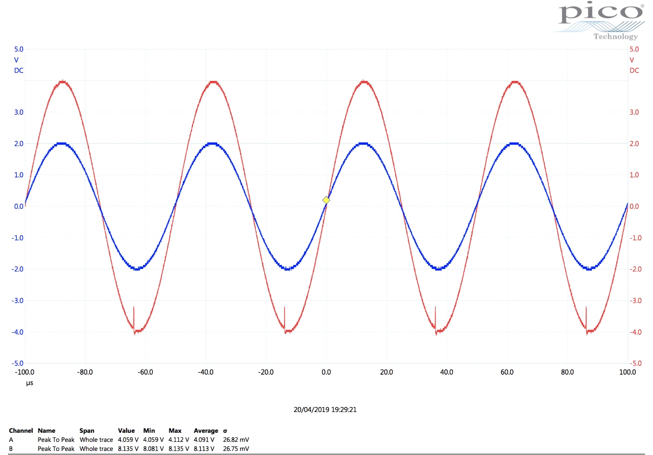
The next scope shot shows the same test setup, but the frequency is increased to 20 kHz. To maintain the 1 A output, you can see that the input voltage has been increased to 4.059 V with a corresponding output of 8.135 V. The amplifier gain is 2.00, comparable to the previous test. A small level of distortion can be seen to be developing at the bottom of the negative cycle of the output waveform.
The final scope capture shows four screenshots of the 20 kHz test applied to the 40 turn coil with the output current increased from 1 A up to 1. 47A. The level of distortion is seen to increase as the current delivered is also increased.

There are a few of ways I have thought of to overcome this. An improvement can be made by removing the 1 ohm resistor in the output circuit, this will allow me to use the full output voltage of the amplifier across the coil. This will however, reduce the level of control for low output currents, as my Rigol DG1022 waveform generator is not that stable at low outputs, this might not be a good idea.
I could increase the output voltage of the amplifier, this would involve a redesign of the board and case, as I would need a larger transformer. It is something to consider for the future, but at the moment I want to try and stick with the existing build.
I can try and make the coils physically smaller. This will be constrained by the size of the current clamps I need to feed through it, but as the original coils were just wrapped around bits of pipe I had lying around at the time, there is some room for improvements here.
I have some 25 mm conduit and straight couplers for wiring up my new garage. The 25 mm conduit is too small to go over the Rigowski coil, but the couple will fit over. I have wound three new coils based around these formers.
What was supposed to be a 20 turn coil, but ended up as 18 turns, has been wound around a coupler that has been left in place, so this coil has a slightly larger diameter. 40 turn and 100 turn coils have been wound around the 25 mm conduit, the turns glued together and then removed from the conduit former. These are the smallest diameter coils I can achieve for this application. The photo below shows how the 40 turn coil fits over the Rogowski coil.

This photo shows the difference between the physical size of the new and old coils.

The 18 and 40 turn coils are single layer, but to keep the overall length down on the 100 turn coil, I have made this a 3 layer coil.
As part of my investigation into the coil design, I looked around for some calculation software so that I could adjust parameters theoretically before committing to physically making the coil and I found this rather useful piece of software called ‘Coil32’
This is freely available for download in Windows, MacOS, Linux and Android versions.
It is primarily aimed at radio hams, but works very well for the single-layer coils that I am producing. It did not work so well for the multi-layer coil, but the calculation parameters available were different to what I actually built, which would explain the disparity.
Below is the output of the calculator for the 40 turn coil at a frequency of 50Hz.

I compared the results of the calculator to the results of measurements made after the coil had been wound. The measurements were made with an Applent AT2817A LCR meter. From the table below, you can see how accurate the measurements are against the calculations from the software for both resistance and inductance.

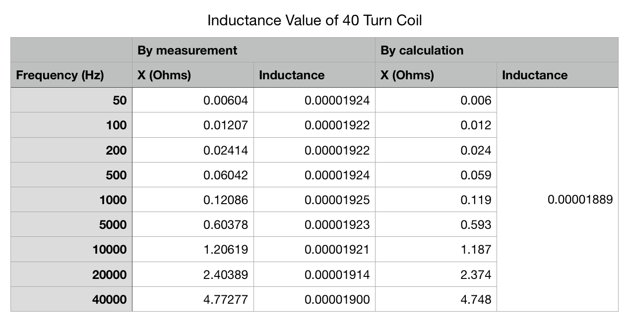
Having this piece of software, greatly reduced the time required to see what effects changing coil parameters would have on the impedance seen by the amplifier.
I then set the new 40 turn coil up on the amplifier and recorded waveform captures at each of the test currents used on the old larger diameter coil.
As can be seen very little distortion is seen on the output waveform. On the old coil for a 1.50 A current, the input was at 16.6 V and the output at 26.4 V. With the new smaller diameter coil, this has now dropped to 7.04 V input and 13.5 V output.

This would imply that I would be able to get more current through the coil before reaching the output limitations of the amplifier. At 2.0 A output, a stable output can still be achieved at 20kHz. Increasing the output to 2.21 A and distortion starts to occur in the output waveform as seen below.


The 1.0mm wire can take a maximum current in the region of 3.2 A, but the original amplifier design was limited to 2.0 A. So it looks like I will need to do more work on the amplifier to obtain more current but I am happy with the new 40 turn coil, so I looked into making it a little more mechanically robust.
I have some 4 mm plastic sheet around from another project so I cut off a short section and bent a 90 degree bend into it. This allowed me to mount in two banana plugs to line up with the output jacks on the current amplifier and then I hot glued the coil onto the plastic.


With the new 40 turn coil completed, my attention moved towards a 100 turn coil. My original intention was to wind a multilayer coil, as a single layer of 100 turns would be too long if kept straight. That would give me 33 turns on two layers and 34 turns on one layer. The Coil32 software has options for carrying out calculations on multilayer coils either with or without spacers, but the output is not as detailed as it is for a single layer coil.

The coil was wound around the 25 mm former with some tape built up at the ends to try and keep the coil layers in line. Unfortunately, this did not work very well and the layers collapsed at one end, probably due to the pressure of the winding process.

Electrical tests were carried out on the coil to establish its characteristics.

As can be seen above, the characteristics of the coil were not good for use with the amplifier as it stands. At 20 kHz, the 3 layer coil has nearly 8 times the impedance of the 40 turn coil. I certainly would not be able to push much current through this with the amplifier.
Trying different configurations within the Coil32 program, I decided to revert back to using a single layer coil and also increase the wire diameter from 1.0 mm up to 1.5 mm.

Using this configuration, the impedance at 50 Hz was 12 mOhms increasing up to 4.7 Ohms at 20 kHz. This should be within the capability of the amplifier design to drive 1.0 A through it.
The next problem encountered was winding this coil. The small manual coil winding machine I have can only wind coils up to a maximum of 110 mm long, but this coil as a single layer would be closer to 170 mm long. With a 25mm conduit coupler, I was able to make an extension mounted over the securing nut on the coil winder. Luckily enough I have a slim vortex socket set that could tighten up the securing nut inside the coupler, being hollow by design the vortex socket was not stopped by the threaded bar of the coil winder as a normal socket would have been.
| {gallery} Winding new 100 turn coil |
|---|
Extension piece mounted on coil winder |
Draper hollow design Vortex socket and ratchet |
Tightening up the securing nut inside the extension |
Starting to wind the coil |
Coil winding completed |
Close-up of completed coil |


The design was a bit wobbly, but with a little care, I managed to wind the coil. Then some fun and games started. The coil was found to be quite springing and was all for trying to unwind itself. Whilst on the former, this was easy to control with some tape at each end, but I wanted to mount the coil in a semi-circle to allow the smaller clamp meter to fit through it.
Another section of plastic was cut to the desired shape and the coil mounted onto it. I secured the coil by feeding the wire ends through the plastic sheet and then holding the coil down in three places with small ty-raps through the plastic and a few of the turns. As the coil fixing was underneath the plastic stand, it had to be raised of the ground with small rubber feet to allow it to sit level.


The coil is a but untidy, partly due to its insistence on unwinding itself. It works well with the Flir CM55 clamp, but it is a little flimsy and whilst the 3000 A coils from LEM and Fluke can be worked through it, it will probably be very easy to damage and I may end up making another 100 turn coil that is a little straighter for those clamps.
The coil was tested in the same manner as the 40 turn coil, first on the LCR meter to gain its electrical characteristics and then secondly with the current amplifier.

The electrical measurements looked good against the calculations form the Coil32 software. The output from the amplifier at 20 kHz, looked good up to 1.5 A, a similar performance to the original 40 turn coil.

Beyond this, interference became more apparent as the current was increased. At 1.565 A, distortion was definitely becoming visible. At 1.75 A, the output was not good at all.


It seems to be clear that the current configuration will struggle at 20 kHz output, with anything over a 4 Ohm load. This leads me to the conclusion that I probably need to look at increasing the output voltage of the amplifier for this to get any better. The alternative to this is to look at operating two amplifiers in series. As I have my amplifier project board set-up this could be relatively easy to investigate. My current understanding is that to do this, I will need to shift the phase of one of the amplifiers, so a greater potential difference is created between them.
As an extension to the amplifier, I think in the next version, I should also look into building in a small sine wave generator, to dispense with the use of the Rigol waveform generator. This will make it into a more complete solution, without the reliance on some of the external apparatus.
Top Comments