element14 Community
element14 Community
    Register Log In
  • Site
  • Search
  • Log In Register
  • About Us
  • Community Hub
    Community Hub
    • What's New on element14
    • Feedback and Support
    • Benefits of Membership
    • Personal Blogs
    • Members Area
    • Achievement Levels
  • Learn
    Learn
    • Ask an Expert
    • eBooks
    • element14 presents
    • Learning Center
    • Tech Spotlight
    • STEM Academy
    • Webinars, Training and Events
    • Learning Groups
  • Technologies
    Technologies
    • 3D Printing
    • FPGA
    • Industrial Automation
    • Internet of Things
    • Power & Energy
    • Sensors
    • Technology Groups
  • Challenges & Projects
    Challenges & Projects
    • Design Challenges
    • element14 presents Projects
    • Project14
    • Arduino Projects
    • Raspberry Pi Projects
    • Project Groups
  • Products
    Products
    • Arduino
    • Avnet Boards Community
    • Dev Tools
    • Manufacturers
    • Multicomp Pro
    • Product Groups
    • Raspberry Pi
    • RoadTests & Reviews
  • Store
    Store
    • Visit Your Store
    • Choose another store...
      • Europe
      •  Austria (German)
      •  Belgium (Dutch, French)
      •  Bulgaria (Bulgarian)
      •  Czech Republic (Czech)
      •  Denmark (Danish)
      •  Estonia (Estonian)
      •  Finland (Finnish)
      •  France (French)
      •  Germany (German)
      •  Hungary (Hungarian)
      •  Ireland
      •  Israel
      •  Italy (Italian)
      •  Latvia (Latvian)
      •  
      •  Lithuania (Lithuanian)
      •  Netherlands (Dutch)
      •  Norway (Norwegian)
      •  Poland (Polish)
      •  Portugal (Portuguese)
      •  Romania (Romanian)
      •  Russia (Russian)
      •  Slovakia (Slovak)
      •  Slovenia (Slovenian)
      •  Spain (Spanish)
      •  Sweden (Swedish)
      •  Switzerland(German, French)
      •  Turkey (Turkish)
      •  United Kingdom
      • Asia Pacific
      •  Australia
      •  China
      •  Hong Kong
      •  India
      •  Korea (Korean)
      •  Malaysia
      •  New Zealand
      •  Philippines
      •  Singapore
      •  Taiwan
      •  Thailand (Thai)
      • Americas
      •  Brazil (Portuguese)
      •  Canada
      •  Mexico (Spanish)
      •  United States
      Can't find the country/region you're looking for? Visit our export site or find a local distributor.
  • Translate
  • Profile
  • Settings
Personal Blogs
  • Community Hub
  • More
Personal Blogs
Frank Milburn's Blog PCB for a Kelvin (4-Wire) Milliohm Meter
  • Blog
  • Documents
  • Mentions
  • Sub-Groups
  • Tags
  • More
  • Cancel
  • New
  • Share
  • More
  • Cancel
Group Actions
  • Group RSS
  • More
  • Cancel
Engagement
  • Author Author: fmilburn
  • Date Created: 18 Oct 2018 5:49 AM Date Created
  • Views 9475 views
  • Likes 13 likes
  • Comments 112 comments
  • kelvin measurement
  • current source
  • 4 wire measurement
  • milliohm measurement
  • op amps
Related
Recommended

PCB for a Kelvin (4-Wire) Milliohm Meter

fmilburn
fmilburn
18 Oct 2018

EDIT 24 Oct 2018  The schematic in this post contains an error.  It will be reposted after receipt of the PCB and testing.


I am developing an inexpensive but reasonably accurate meter for measuring resistance in the milliohm range.  The previous posts are listed in the related links at the bottom.  In this post the design for the working prototype is expanded to include a second current source for measuring resistance up to 400 ohm and provision made for future auto-ranging.  A new schematic and a PCB design are presented along with an update on meter options.


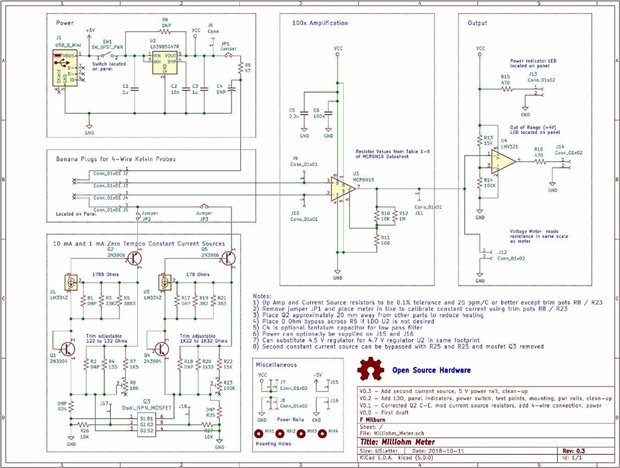
Revised Schematic

The revised schematic is shown below:

image

The added current source is identical to the first but designed for 1 mA current.  A dual N-Channel MOSFET with pull-down resistors is connected just above ground to allow selection of a source.  It will add maybe an ohm to ground.  There are jumpers and bypass resistors so that the second current source and MOSFETs can be omitted if desired.  This has not been incorporated into the working prototype so a second eye and comments on the design are welcome.  An additional 5V set of pins was added so a source other than the USB connection could be used as well.  Thanks for ideas and suggestions shabaz  image.

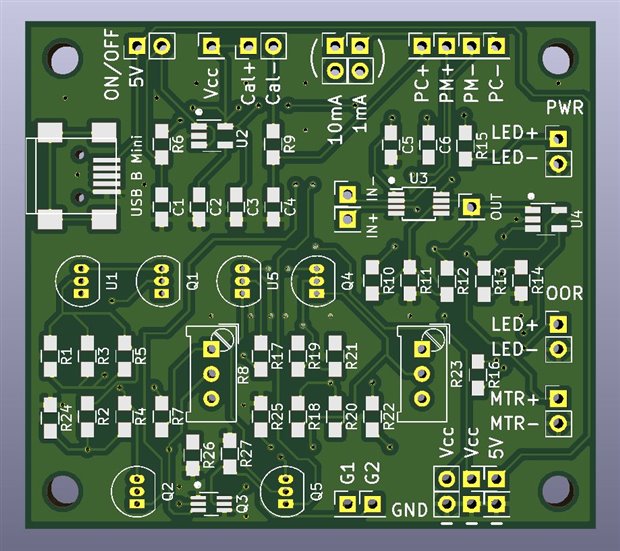
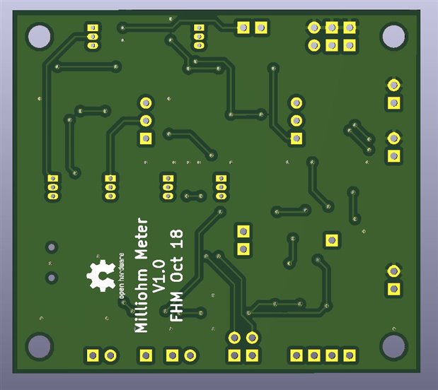
PCB Design

The PCB was done in KiCad (5.0.0) which is a new version for me and I am still finding my way around the changes.  The layout was done with ease of hand soldering in mind which led to what I consider poor routing so I may redo it and hope send it to the board house tomorrow.  There were a couple of unfinished wires when the renders below were made but those are finished now and it passes electrical check.

image

image


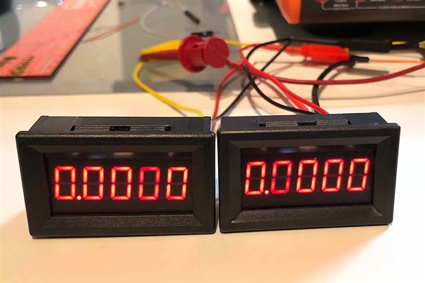
Panel Meters and Alternate Current Sources

The panel meter I ordered from China came in earlier in the week but they were a disappointment.  Although they advertised 5 digit resolution they are not much better than 3 and show zero when down in the low millivolt range so they aren't much use for this project.  There is a zeroing procedure which I tried without much luck and a small pot which doesn't seem to do much.  I also ordered a ammeter but haven't had a chance to really test it.  It looks like I will be using patch cables and a multimeter for the display.

image


I also finally got the other current sources I was going to test for the project but time is running out and the LM334 really works good so I will put those aside for a later time.


Next Steps

This week I also plan to finish preparation of the BOM and order the parts that aren't in hand but there probably won't be any more posts until after the PCBs are back in about 2 weeks time.  As always, comments and corrections are appreciated.


Related Links

Testing Current Sources for a Kelvin (4-Wire) Milliohm Meter

More on Current Sources and a Kelvin (4-Wire) Milliohm Meter

Even More on Current Sources and a Kelvin (4-Wire) Milliohm Meter

Working Prototype of a Kelvin (4-Wire) Milliohm Meter

  • Sign in to reply

Top Comments

  • fmilburn
    fmilburn over 6 years ago +7
    Hi Shabaz, From you description, it looks like I ordered the wrong meter... Could also have a particularly bad sample. I spent a fair amount of time trying to calibrate it again this evening without luck…
  • shabaz
    shabaz over 6 years ago in reply to fmilburn +7
    Hi Frank, Some good news, and some uncertainty : ) The good news is that it is assembled, it was a breeze using the PCB. Also it is just the right size for the enclosure, it all fits hopefully : ) I've…
  • shabaz
    shabaz over 6 years ago +6
    Hi Frank, Sorry to hear the panel meters were no good : ( I'll check the ones I have, in case any function better. (By the way from the back of it, if there is a 5 or 6-pin SOT-23, that should have been…
Parents
  • shabaz
    shabaz over 6 years ago

    I started building this tonight : )

    I've soldered all the resistors and pots, and then trimmed to the desired resistance.

    Hopefully tomorrow I'll get the rest all soldered up, and try powering it up before putting it in the case!

    • Cancel
    • Vote Up +3 Vote Down
    • Sign in to reply
    • More
    • Cancel
  • fmilburn
    fmilburn over 6 years ago in reply to shabaz

    I was just discussing the project with my fellow geek friend this evening and told him I hoped you would have a chance to look at it soon.  Let me know your thoughts and upgrades and I will incorporate when I respin the board.

    • Cancel
    • Vote Up +3 Vote Down
    • Sign in to reply
    • More
    • Cancel
  • shabaz
    shabaz over 6 years ago in reply to fmilburn

    Hi Frank,


    Some good news, and some uncertainty : )

    The good news is that it is assembled, it was a breeze using the PCB. Also it is just the right size for the enclosure, it all fits hopefully : ) I've yet to cut out the front panel.

    I used slightly different resistor values to you, for both the 10mA and 1mA ranges, in order to account for the PN junction Vf value at those currents, and the very slightly different tempco value at these two settings too. And it appears rock-solid, even without the enclosure, unlike the earlier attempt I tried to replicate, where I needed a bowl and waiting ages for it to settle. For the quarter of an hour, since switch-on, the display has been reading 0.1599 or 0.1600.

    The uncertainty/bad news is, that this value isn't correct : ( it should be reading 0.164 since there is a 164mohm resistance. The problem is that the current isn't 10mA : ( it is about 9.7mA (I measured it using the pins you have on the PCB for that purpose). At approx 9.7mA, the measured value of a 164mohm resistance would indeed be 160mohm.

    The error is not caused by resistor tolerance, this is way too large for that : (

    Also, when I switch to the higher resistance range, I see 0.97mA. So whatever mistake I'm making, it is the same for both ranges.

    So, I guess there is some misinterpretation of the datasheet formula : ( but I can't see what. I'll look more closely into that tomorrow.

    These are the values I'm using for the 10mA range which is giving me about 9.7mA:

    image

    I can't just use the trimmer to adjust the current, since that would throw the temp drift cancellation out the window : (

    I guess I could just set the "Desired current" in the spreadsheet to something proportionately larger, and that will solve the problem, since I'm seeing the same ratio of error at 1mA as at 10mA. But still it would be nice to know why this is the case : (


    image

    • Cancel
    • Vote Up +7 Vote Down
    • Sign in to reply
    • More
    • Cancel
Comment
  • shabaz
    shabaz over 6 years ago in reply to fmilburn

    Hi Frank,


    Some good news, and some uncertainty : )

    The good news is that it is assembled, it was a breeze using the PCB. Also it is just the right size for the enclosure, it all fits hopefully : ) I've yet to cut out the front panel.

    I used slightly different resistor values to you, for both the 10mA and 1mA ranges, in order to account for the PN junction Vf value at those currents, and the very slightly different tempco value at these two settings too. And it appears rock-solid, even without the enclosure, unlike the earlier attempt I tried to replicate, where I needed a bowl and waiting ages for it to settle. For the quarter of an hour, since switch-on, the display has been reading 0.1599 or 0.1600.

    The uncertainty/bad news is, that this value isn't correct : ( it should be reading 0.164 since there is a 164mohm resistance. The problem is that the current isn't 10mA : ( it is about 9.7mA (I measured it using the pins you have on the PCB for that purpose). At approx 9.7mA, the measured value of a 164mohm resistance would indeed be 160mohm.

    The error is not caused by resistor tolerance, this is way too large for that : (

    Also, when I switch to the higher resistance range, I see 0.97mA. So whatever mistake I'm making, it is the same for both ranges.

    So, I guess there is some misinterpretation of the datasheet formula : ( but I can't see what. I'll look more closely into that tomorrow.

    These are the values I'm using for the 10mA range which is giving me about 9.7mA:

    image

    I can't just use the trimmer to adjust the current, since that would throw the temp drift cancellation out the window : (

    I guess I could just set the "Desired current" in the spreadsheet to something proportionately larger, and that will solve the problem, since I'm seeing the same ratio of error at 1mA as at 10mA. But still it would be nice to know why this is the case : (


    image

    • Cancel
    • Vote Up +7 Vote Down
    • Sign in to reply
    • More
    • Cancel
Children
  • jw0752
    jw0752 over 6 years ago in reply to shabaz

    Hi Shabaz,


    I don't have the skills to make a suggestion but one thing that has caused me problems when using these meters in the fairly low input impedance for a voltmeter, Some of them are as low as 75K. I don't know if this is a factor for your tests and I could find no reference to it in the notes above. Just thought I would mention it.


    John

    • Cancel
    • Vote Up +4 Vote Down
    • Sign in to reply
    • More
    • Cancel
  • fmilburn
    fmilburn over 6 years ago in reply to shabaz

    Hi Shabaz,


    I actually noticed something similar on mine and should have taken more notice...  This is taken from the comments I made above:


         2) The trim pot had insufficient range to adjust the current - had to reduce the resistance so R2 and R1 came in handy.


    This did not occur when I built the prototype on perf board.  I was using the same digital multimeter in both cases to measure the voltage.  Agree it would be nice to figure out what is going on...


    Frank

    • Cancel
    • Vote Up +3 Vote Down
    • Sign in to reply
    • More
    • Cancel
  • fmilburn
    fmilburn over 6 years ago in reply to shabaz

    BTW, It looks really nice in that enclosure!

    • Cancel
    • Vote Up +2 Vote Down
    • Sign in to reply
    • More
    • Cancel
  • shabaz
    shabaz over 6 years ago in reply to jw0752

    Hi John!


    Thanks for the suggestion. I'll check in more detail tomorrow, I can isolate the amplifier and meter circuit easily. The meter I'm using has 350k input resistance, so hopefully not loading the amplifier much. I think you'd enjoy building and testing this circuit by the way : )

    • Cancel
    • Vote Up +3 Vote Down
    • Sign in to reply
    • More
    • Cancel
  • shabaz
    shabaz over 6 years ago in reply to fmilburn

    Hi Frank!


    Ohh that's interesting. Was the current lower for you too?

    If I cannot spot a calculation error by tomorrow, I'll plug in different values into the spreadsheet to scale the voltage up, and test that.. perhaps the datasheet is wrong : ( although it should have been spotted by now, since it is not a new part.. or maybe we've made some incorrect assumption somewhere : ( We could ask on the TI forum.

    Once working values are figured out, then maybe the trip pots are not needed in the rev 2 PCB at all, if you're planning to release a future revision.

    There are some ideas (mainly cosmetic) below, but the current rev 1 PCB is very usable, it accommodates most things, I felt the PCB design is extremely flexible.


    1. The trimmer pot component outline seems slightly offset to the actual Bourns pot physical outline

    2. Change R9 to be 10 ohm (reduces the volt drop)

    3. Change C4 to be 1uF (to add a filter)

    4. Add 100nF decoupling near U4

    5. Might be better to space out the pins for the TO-92 package, for the transistors. But no real need, so if there isn't space, this suggestion should be ignored. For the LM334, the spacing is fine.

    6. It wasn't clear where to obtain power for the panel meter. The connection marked +5V was used, since the panel meter prefers that voltage or higher. But the +5V connection is before the power switch, so if I had used a power switch, then the panel meter would have stayed lit (I didn't solder a power switch).

    7. Maybe have an option to use a DC power jack instead of USB (i.e. have both footprints perhaps, or just pins for soldering flying leads). For my version, I didn't solder a USB connector, but used a DC connector soldered on flying leads.

    8. Shield of USB connector should be connected to 0V perhaps. Would make a nice place to clip a scope or meter 0V connection.

    9. Maybe no need for jumper JP2 and JP3, and alow a SPDT switch to be wired to a new connector at R24 and R25 and ground.

    11. The labels that are on the PCB should also be on the schematic, because it was confusing understanding which ones related to which part of the schematic, e.g. Cal+ and Cal- are not marked on the schematic; they are marked as JP1 on the schematic

    12. Change the kelvin connection labels to Hcur, Hsense, Lcur, Lsense or similar perhaps, maybe on underside of the PCB.

    13. Add a 0-ohm resistor in the connection between the op-amp and the comparator, so that it can be desoldered and isolated for testing (i.e. still have the meter connected, but not the comparator circuit)

    14. Maybe no need for the power LED, since the panel meter will be lit.

    15. Possibly change U4 to LMV7271MF (it is pin-compatible, the footprint can remain the same). I have not tested this yet, I've left U4 currently unpopulated.

    • Cancel
    • Vote Up +3 Vote Down
    • Sign in to reply
    • More
    • Cancel
element14 Community

element14 is the first online community specifically for engineers. Connect with your peers and get expert answers to your questions.

  • Members
  • Learn
  • Technologies
  • Challenges & Projects
  • Products
  • Store
  • About Us
  • Feedback & Support
  • FAQs
  • Terms of Use
  • Privacy Policy
  • Legal and Copyright Notices
  • Sitemap
  • Cookies

An Avnet Company © 2025 Premier Farnell Limited. All Rights Reserved.

Premier Farnell Ltd, registered in England and Wales (no 00876412), registered office: Farnell House, Forge Lane, Leeds LS12 2NE.

ICP 备案号 10220084.

Follow element14

  • X
  • Facebook
  • linkedin
  • YouTube