


9 August 19 Update:
8 July 19 Update: A protoboard was populated for further testing and described at the bottom of the post
I have wanted to build a programmable DC load for some time and have followed both this one by Jan Cumps et. al. and also this one by John Wiltrout. After lots of thought and no action I decided yesterday to just build something with what was on hand.
Specifications
- Max 15V input and 2.5 Amps
- Min 1.8V and 0 Amps
- Resolution 1 mA
- Deliver 10 mA +/- 1 mA
- 5V or USB to power
- User interface: encoder, buttons, and LCD
- Simple to build, probably will not have a PCB made
- Arduino IDE to make it accessible to others
Concept Demonstration
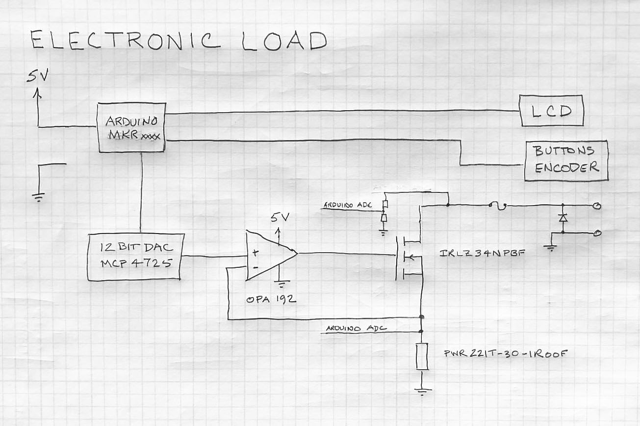
What was on hand is shown in the following schematic:
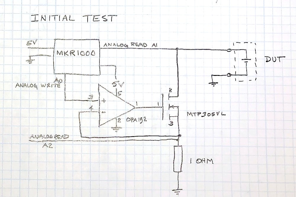
An Arduino MKR1000 output a voltage using the built-in 10 bit DAC which through an OPA192 op amp and MTP305VL MOSFET control the voltage above the 1 ohm resistor. One volt output from the MKR1000 equals one amp to the device under test. In this case the DUT is a 18650 battery hooked up to a boost converter to give roughly 3 Volts.
I was surprised at how good the DAC was on the MKR1000. The MKR1000 ADC had an offset of around 18 mV. Not shown on the schematic above are digital multimeters measuring the input voltage from the DUT, the output voltage from the DAC, and the voltage across the 1 ohm resistor. Tests were run at 10 mA, 50 mA, 100 mA, and 1000 mA where it was discovered that the voltage output of the DUT was dropping quickly.
Arduino Code
[code]
/*
 * Fixed Value Test of DC Electronic Load
 * Tested on MKR1000
 * Frank Milburn
 * June 2019
 *
 * Released into Public Domain
 *
*/
const int DAC_PIN = DAC0;     // output to opamp
const int VOLT_PIN = A1;      // input from DUT
const int CURRENT_PIN = A2;   // input from current setting resistor
const int CURRENT = 1000;       // current in mV   WARNING!!! do not set above 3300!!!
void setup() {
  Serial.begin(115200);
  analogWriteResolution(10);
  analogReadResolution(12);
  pinMode(VOLT_PIN, INPUT);
  pinMode(CURRENT_PIN, INPUT);
}
void loop() {

  unsigned int dacValue = 0;
  dacValue = map(CURRENT, 0, 3267, 0, 1023);
  analogWrite(DAC_PIN, dacValue);
  Serial.print("Current setting = ");
  Serial.print(CURRENT);
  Serial.println(" mA");

  unsigned int inputVoltage;
  inputVoltage = map(analogRead(VOLT_PIN), 0, 4095, 0, 3267);
  Serial.print("Voltage input =   ");
  Serial.print(inputVoltage);
  Serial.println(" mV");

  unsigned int currentReading;
  currentReading = map(analogRead(CURRENT_PIN), 0, 4095, 0, 3267);
  Serial.print("Raw = ");
  Serial.print(analogRead(CURRENT_PIN));
  Serial.print("  Current reading =   ");
  Serial.print(currentReading);
  Serial.println(" mV (mA)")
;
  delay(5000);
}
[/code]
Results
10 mA

DAC output: 10.9 mA
DUT voltage: 3.295 V
Current: 11 mA
Error: 1 mA
50 mA
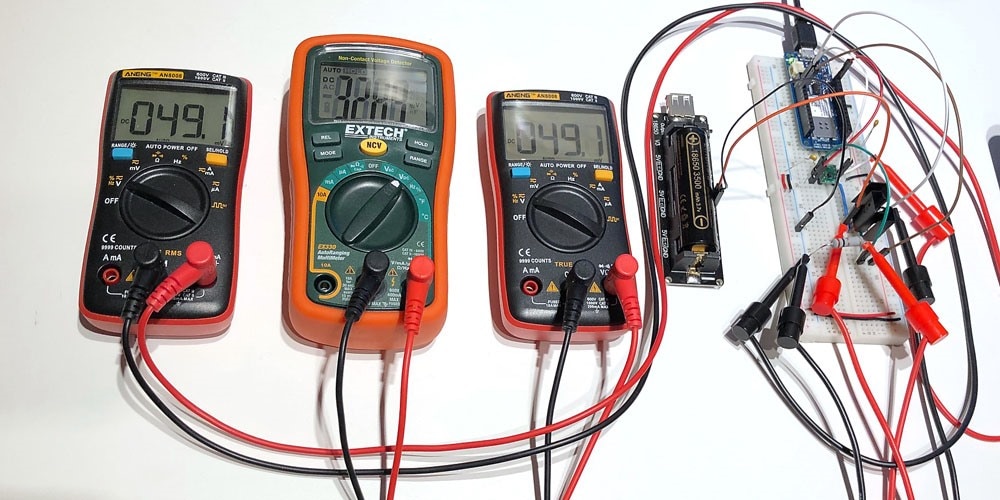
DAC output: 49.1 mV
DUT voltage: 3.289 V
Current: 49.1 mA
Error: 0.9 mA
100 mA
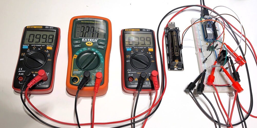
DAC output: 99.8 mV
DUT voltage: 3.271 V
Current: 99.1 mA
Error: 0.9 mA
1000 mA
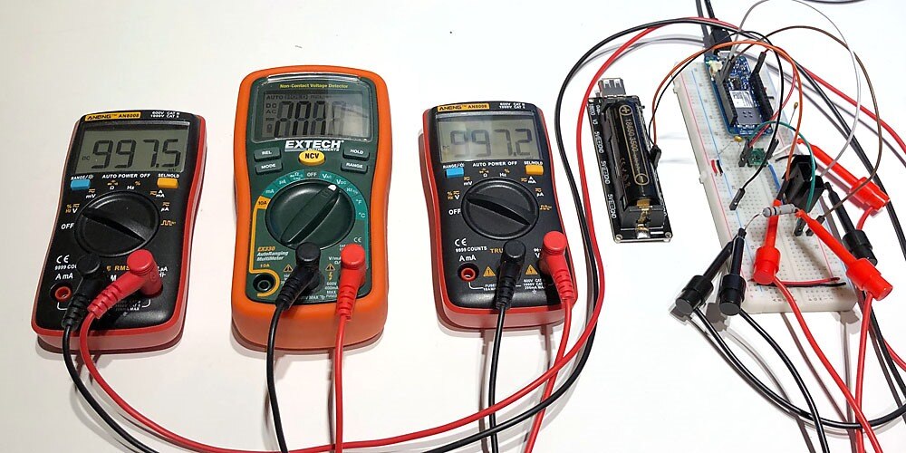
DAC output: 997.5 mV
DUT voltage: 2.89 V
Current: 997.2 mA
Error: 2.8 mA
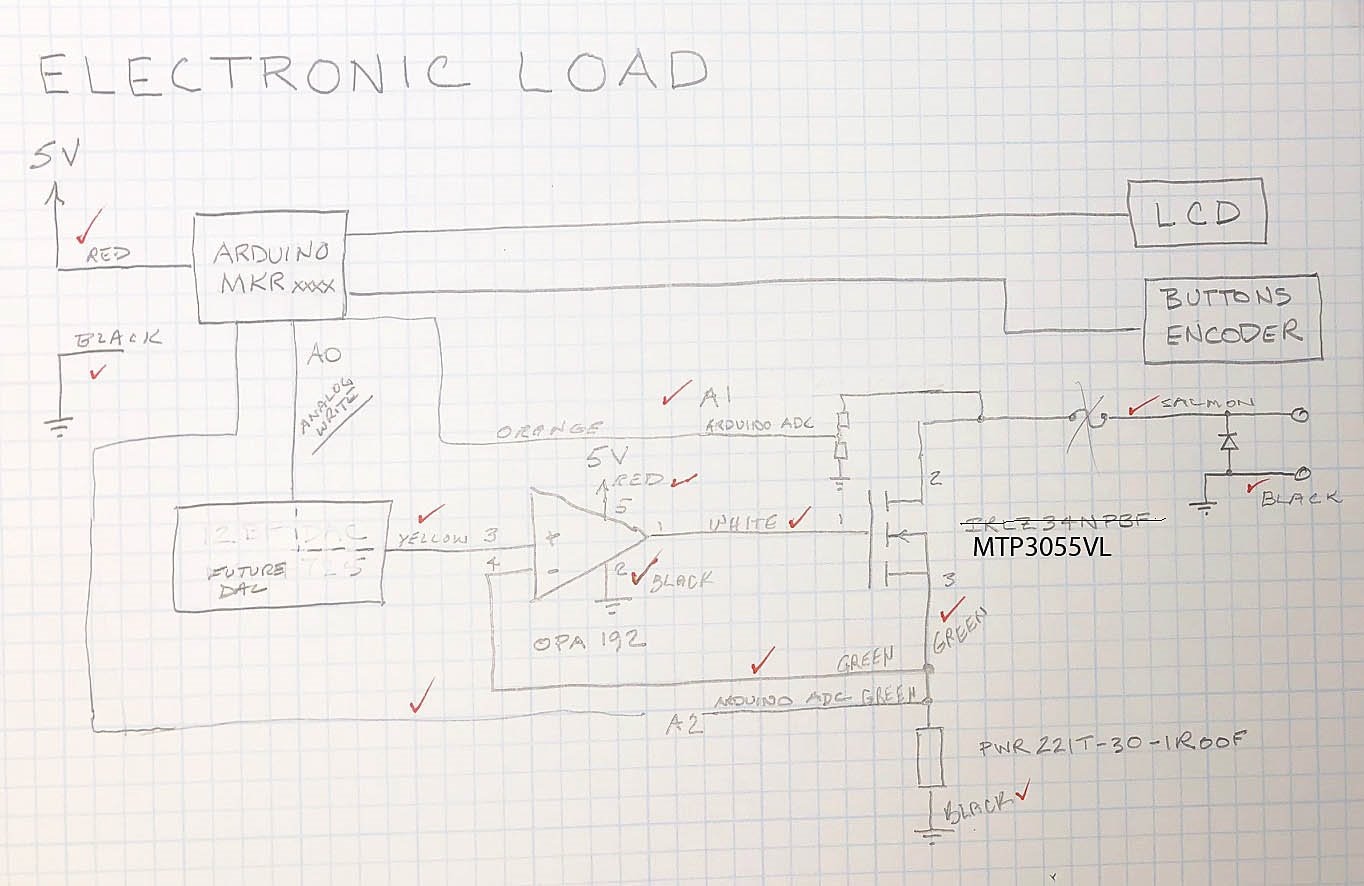
Next Revision
Although the full range was not tested, this was a promising beginning especially since there was no tuning. Here are a couple of areas to work on for the next iteration:
- 12 bit or more DAC (this one gives ~ 3 mA resolution)
- move ADC off board
- Precision resistor (0.98 ohm 3 watt of unknown tempco was used)
- Replace MTP3055VLMTP3055VL with a more modern part
- Add overcurrent and reverse polarity protection
- Add user interface
- Add heat sinks / cooling fan
8 July 19 Update
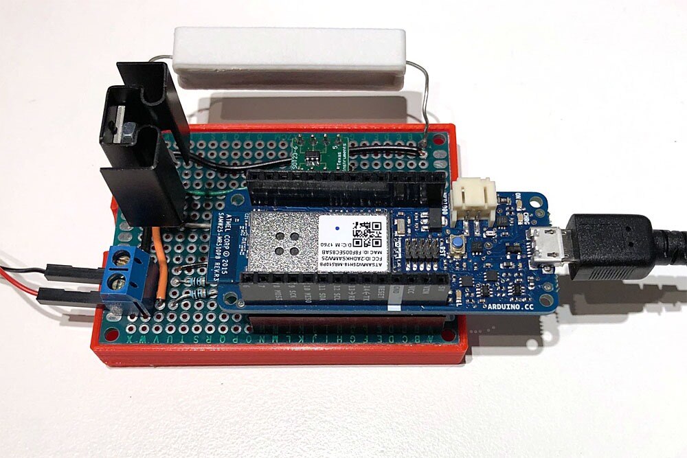
I soldered a little protoboard to play with before deciding what to do next. The idea was to make something more reliable mechanically and allow some thermal testing and firmware development. The design still uses the DAC on the Arduino MKR1000 , OPA192 op amp and the MTP3055VLMTP3055VL MOSFET. The one ohm resistor was picked up cheap locally and measures 1.003 ohms using the milliohm meter.
Female headers were soldered in so that the parts can be easily removed and reused in future.
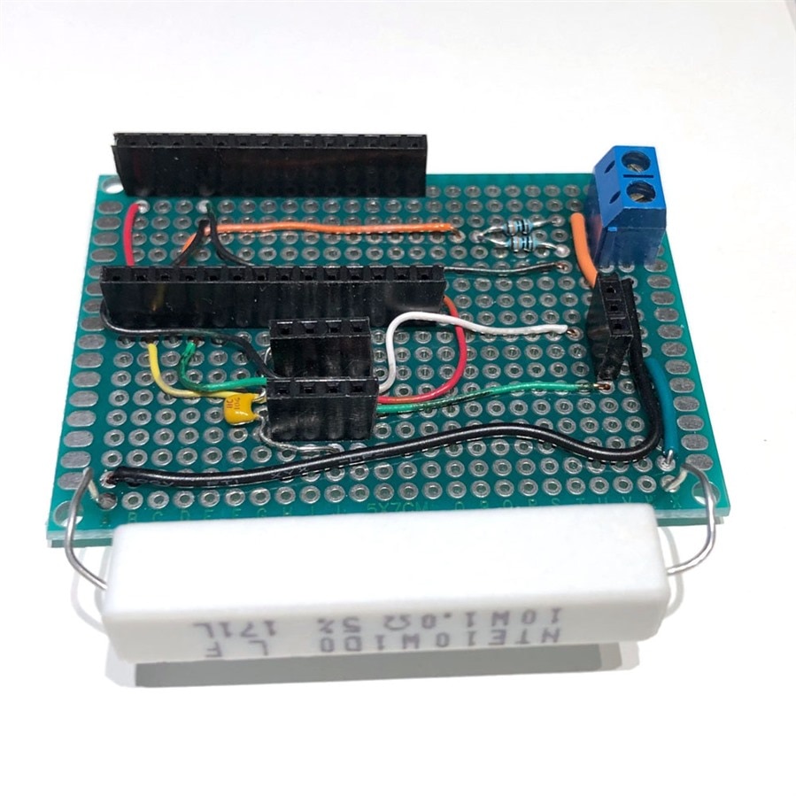
Here it is populated.
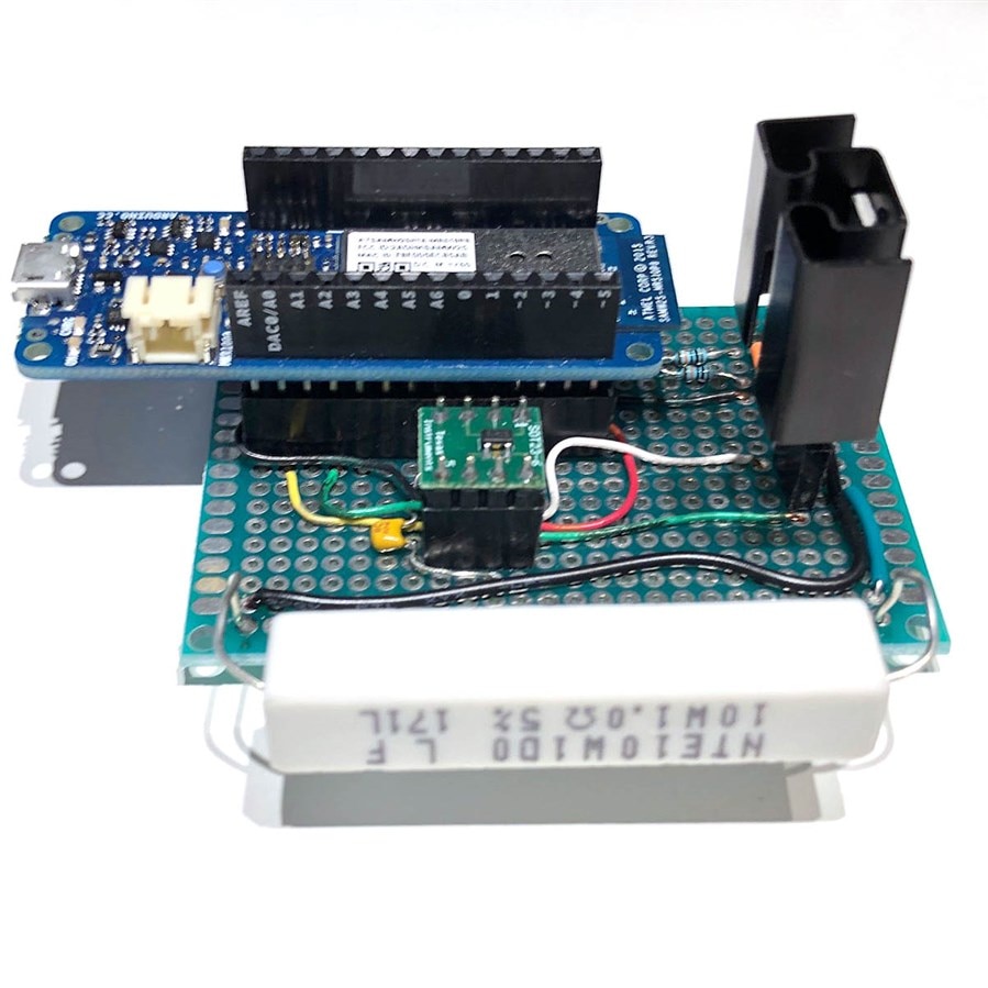
If you have a 3D printer, then you have to print stuff. Here it is in a little tray.
After fixing a wiring mistake where I confused pin 5 on the op amp with pin 5 on the carrier board (pin 5 on the op amp leads to pin 6 on the carrier) everything was working. There seems to be an intermittent bad connection between 5V on the MKR1000 and the op amp - one of the main reasons the board was constructed was to avoid this!. The DAC is accurate in the range tested so far as is A1 which measures the input voltage. A2 which measures the voltage (and thus current) just above the resistor has about 17 mV offset which seems high but I should consult the datasheet to see if it is in spec. It can be corrected in firmware.
Next Revision
It may be a while before I get back to this which is why this interim step is being documented. Thoughts for the next revision...
- Design a PCB to improve mechanical connections, provide a ground plane, and reduce unwanted capacitance
- 12 bit or more DAC (MKR1000 has ~ 3 mA resolution with 3A design)
- move ADC off board (more accuracy, less offset)
- Precision resistor or at least experiment with tempco of resistor on prototype.
- Replace MTP3055VLMTP3055VL with a more modern part
- Add overcurrent and reverse polarity protection
- Add user interface
- Add heat sinks / cooling fan
- Use new Keysight scope with signal generator to investigate issues outlined by Michael Kellett in comments
8 Jul 2019: update progress
9 Jul 2019: corrected some typos
Links
Programmable DC Electronic Load - Follow-up A follow-up to this post
https://www.element14.com/community/docs/DOC-83867/l/programmable-electronic-load
Top Comments
-

fmilburn
-
Cancel
-
Vote Up
+4
Vote Down
-
-
Sign in to reply
-
More
-
Cancel
-

michaelkellett
in reply to fmilburn
-
Cancel
-
Vote Up
+3
Vote Down
-
-
Sign in to reply
-
More
-
Cancel
-

fmilburn
in reply to michaelkellett
-
Cancel
-
Vote Up
+3
Vote Down
-
-
Sign in to reply
-
More
-
Cancel
Comment-

fmilburn
in reply to michaelkellett
-
Cancel
-
Vote Up
+3
Vote Down
-
-
Sign in to reply
-
More
-
Cancel
Children