element14 Community
element14 Community
    Register Log In
  • Site
  • Search
  • Log In Register
  • Community Hub
    Community Hub
    • What's New on element14
    • Feedback and Support
    • Benefits of Membership
    • Personal Blogs
    • Members Area
    • Achievement Levels
  • Learn
    Learn
    • Ask an Expert
    • eBooks
    • element14 presents
    • Learning Center
    • Tech Spotlight
    • STEM Academy
    • Webinars, Training and Events
    • Learning Groups
  • Technologies
    Technologies
    • 3D Printing
    • FPGA
    • Industrial Automation
    • Internet of Things
    • Power & Energy
    • Sensors
    • Technology Groups
  • Challenges & Projects
    Challenges & Projects
    • Design Challenges
    • element14 presents Projects
    • Project14
    • Arduino Projects
    • Raspberry Pi Projects
    • Project Groups
  • Products
    Products
    • Arduino
    • Avnet & Tria Boards Community
    • Dev Tools
    • Manufacturers
    • Multicomp Pro
    • Product Groups
    • Raspberry Pi
    • RoadTests & Reviews
  • About Us
  • Store
    Store
    • Visit Your Store
    • Choose another store...
      • Europe
      •  Austria (German)
      •  Belgium (Dutch, French)
      •  Bulgaria (Bulgarian)
      •  Czech Republic (Czech)
      •  Denmark (Danish)
      •  Estonia (Estonian)
      •  Finland (Finnish)
      •  France (French)
      •  Germany (German)
      •  Hungary (Hungarian)
      •  Ireland
      •  Israel
      •  Italy (Italian)
      •  Latvia (Latvian)
      •  
      •  Lithuania (Lithuanian)
      •  Netherlands (Dutch)
      •  Norway (Norwegian)
      •  Poland (Polish)
      •  Portugal (Portuguese)
      •  Romania (Romanian)
      •  Russia (Russian)
      •  Slovakia (Slovak)
      •  Slovenia (Slovenian)
      •  Spain (Spanish)
      •  Sweden (Swedish)
      •  Switzerland(German, French)
      •  Turkey (Turkish)
      •  United Kingdom
      • Asia Pacific
      •  Australia
      •  China
      •  Hong Kong
      •  India
      •  Korea (Korean)
      •  Malaysia
      •  New Zealand
      •  Philippines
      •  Singapore
      •  Taiwan
      •  Thailand (Thai)
      • Americas
      •  Brazil (Portuguese)
      •  Canada
      •  Mexico (Spanish)
      •  United States
      Can't find the country/region you're looking for? Visit our export site or find a local distributor.
  • Translate
  • Profile
  • Settings
Personal Blogs
  • Community Hub
  • More
Personal Blogs
John Wiltrout's Blog Extreme Solder Iron Upgrade
  • Blog
  • Documents
  • Mentions
  • Sub-Groups
  • Tags
  • More
  • Cancel
  • New
  • Share
  • More
  • Cancel
Group Actions
  • Group RSS
  • More
  • Cancel
Engagement
  • Author Author: jw0752
  • Date Created: 30 Aug 2015 7:15 PM Date Created
  • Views 2759 views
  • Likes 7 likes
  • Comments 21 comments
  • solder-iron
  • thermistor
  • triac_dimmers
Related
Recommended

Extreme Solder Iron Upgrade

jw0752
jw0752
30 Aug 2015

image


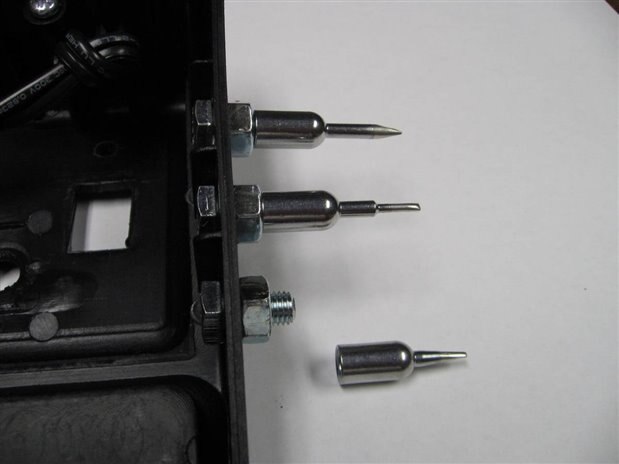
For many years this has been my soldering iron. I have liked it and continued to use it because it gives me a choice of a high 40 watt and a low 20 watt heat setting. I also like the variety, durability, and economy of the tips that are available for it. Here is a link to the type of tips that are used. It is manufactured by Weller but I am pretty sure that it was an Ungar design originally.


http://www.newark.com/weller/pl113/tools-soldering-tips/dp/33F681?ost=Weller+Solder+Tips&categoryId=800000006341


Here is the list of the things that I do not like about it which will be corrected or ameliorated by this modification.


(1) The heat is either too hot or not hot enough for my needs depending on the high - low setting. I can work with the High but it tends to oxidize the solder too quickly which leads to the need for frequent cleaning and re-tinning. The Low setting is ok for very light work but doesn't have the power for larger joints or thick copper traces.


(2) The designer of the solder iron was apparently an artist not a user of solder irons. By designing so that the handpiece wire exits from the back of the unit we get a pretty unit but it is a functional disaster. The problems caused by the wire exiting the unit from the back are: 6 inches of length are lost, the wire is always in jeopardy of being melted by the tip, and the use of the iron causes a torque on the unit that spins it around.


(3) The unit is too light to be stable and is always shifting and moving around when the iron is being used.


These are the goals that will be addressed by the modification:


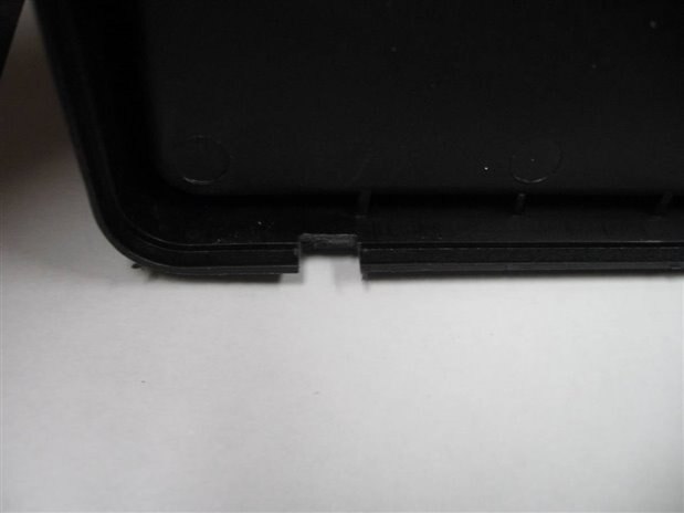
(1) The exit for the handpiece cord will be moved to the front of the solder iron stand.


(2) Weight will be added to the stand to increase its stability.


(3) A triac controlled dimmer circuit will be added to allow the selection of power to the tip of Zero to Forty watts.


(4) Test points will be provided on the outside of the station to calibrate the voltage to the Iron.


(5) A rack to hold the extra tips will be added to the side of the station.


(6) A sensor circuit will be incorporated so that full power is used during warm up and if the solder iron is off the stand for more than a minute.


After a number of tests, breadboarding, and circuit prototypes this is the schematic of the circuit that will be incorporated in the unit.


image


The voltage control to the solder iron is a simple Triac controlled dimmer circuit similar to those used in home light dimming applications. The choice of the Q4015L5 Triac is mearly because I had one from salvage and while it is massive over kill for control of just 40 watts it won't hurt anything either. The sensor part of the circuit was more of a challenge as there is very limited space inside the base of the solder iron. I wanted to sense the temperature of a thermistor mounted on the iron holder so that I could determine if the iron was hot and if it was in the holder. This way full voltage can be applied to the iron until it reaches operational temperature. The full voltage is also restored from the level of control voltage applied when the solder iron is out of the holder and in use for more than a minute. This will give the iron a heat boost when under heavy use. The thermistor voltage divider controls a transistor which in turn controls a relay. The relay turns on the Turbo LED to indicate the iron is under full 120 VAC and it shorts the voltage control potentiometer so as to produce the application of full 120 VAC to the iron. The tags "A" and "B" in the schematic are the connections that short the potentiometer.


The modification was begun by moving the exit for the handpiece wire from the back of the unit to the front. The 1/4 - 28 spare solder tip storage mounting screws were also installed.


image


image


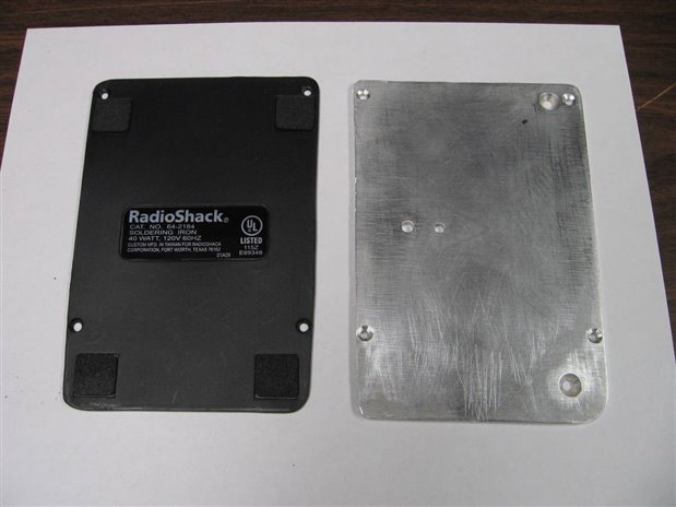
Next a 4mm thick plate of aluminum was cut to match and replace the original plastic base plate of the iron. This aluminum plate will also serve as a heat sink for the Q4015L5 Triac though it will not really be needed.


image


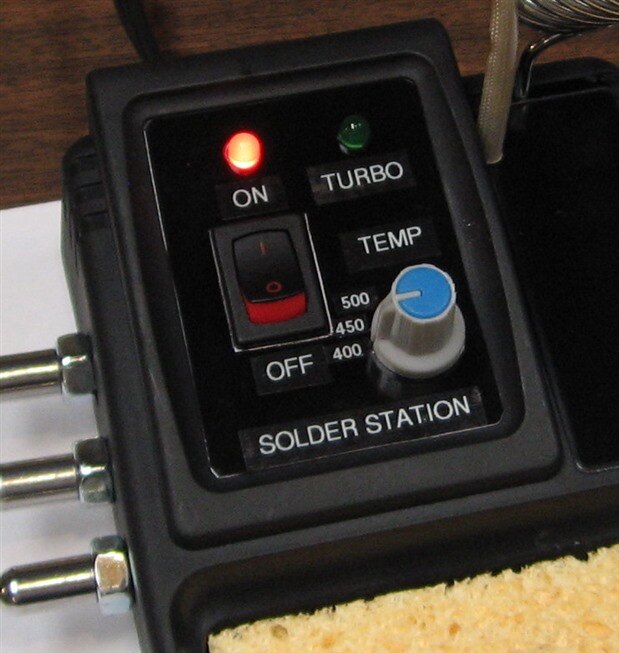
The control, power switch, and LEDs were mounted into the redesigned front panel of the unit and the circuitry for the dimmer was attached to the base plate. The Q4015L5 is an isolated tab device so it was mounted directly without the need for mica or isolating washers.


image


image


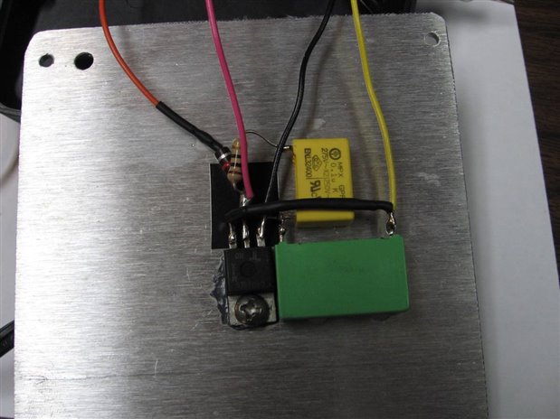
Most of my builds and modifications are design centered on salvage equipment and parts that I have in the shop. In the case of this build nearly every part used is recycled from old boards and equipment. The design of the thermistor sensor circuits is no exception. This part of the circuit was going to need a power supply and testing had shown that 9 volts would be sufficient. Even though a 12 volt relay was to be used the 9 volts was still within the pull in range for the relay. I chose the 12 volt relay as it was the only DPDT configured relay in the box that was small enough for this application. The 9 volt power supply was extracted from a wall wart originally designed to power an Arduino board. For the fun  of it I am going to show my construction mess in the next photo. This is to quash the suspicion that I never make a mess.


image


Here is a picture of the inside of the base of the solder iron after the circuits and components have been situated.


image

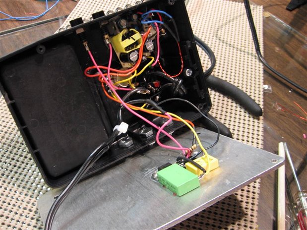
Notice the two jacks at the top of the case. These are pin jacks that will allow me to attach a voltmeter and monitor the voltage across the solder iron's heating element. By monitoring the voltage and the temperature of the tip I will have a rough idea of the temperature that is produce in the iron for a given voltage. The front panel picture (previous displayed) shows the results of this calibration reflected in labels showing approximate degrees Fahrenheit for different control positions.


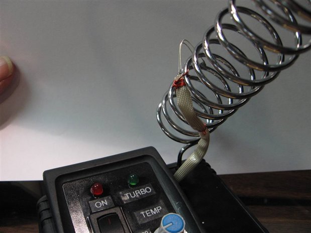
The most difficult part of the design for me was the construction and mounting of the Thermistor sensor on the wire solder iron holder. I had selected a 100K thermistor whose characteristics suited my needs. I used 24 GA enameled wire as the leads from the thermistor. I did not want to have trouble with melting insulation and there was no Teflon wire available in the shop in a small enough gauge. I covered the wiring with a piece of high temperature spaghetti that I had salvaged from a dental sterilizer. The assembly was finally lashed to the solder iron holder with more of the enameled 24 gauge wire. In the following pictures you can see how this assembly was mounted.


image


image


I wish I could say that it was as easy as buttoning it up at this point and testing it but as with most of my projects there were many disasters that had to be overcome. Almost all my disasters are self inflicted but occasionally fate gets me too. For example my first choice for a relay for this project had 8 pins. It was housed in an opaque case so I could not look at the contact configuration. All my experienced said that I had a DPDT relay and so that is the way I wired it. Only after destroying one 9 volt power supply board did I discover that it was really a SPDT relay with the pins to the contacts brought out twice to increase the current capacity of the relay. I actually destroyed a second power supply board when my circuit board extraction technique exceed the mounting specs for a couple components. Finally however all the bugs all fled back into the crevasses of a builders nightmare and I was able to do my final tests.


image


From a cold state the iron would quickly heat up under the full 120 VAC of the Turbo Mode. Once the thermistor sensed a hot iron the Triac dimmer circuit kicked in and voltage dropped to my input setting. First choice was 90 VAC or about half way between the original 20 watt and 40 watt capabilities of the Radio Shack Solder iron. You can see the meter probes monitoring the voltage to the heating element of the solder iron. If the iron is removed from the holder and used to solder something the thermistor begins to cool and as soon as the tipping point is reached, approximately 40 seconds, the Turbo kicks in and a full 120 VAC is applied to the heating element. If the iron is put back into the holder the Turbo turns off within ten seconds and the voltage drops back to Triac control level.


I really enjoy projects that are directed toward improving the operation of the shop. This project was no exception. The verdict is still out on whether I have totally answered my goals. It is likely there will be some side effects of the change that I will have to deal with. Thank you for taking the time to check out this project. If you have any questions on any aspect of the project let me know. If you are new to the world of electronics and want to do something similar to this be aware that the voltages used for solder irons are at mains level and can be dangerous to your health and life if not handled properly.


John


  • Sign in to reply

Top Comments

  • clem57
    clem57 over 10 years ago +1
    I think you are Mr. Tinkerer! Nice blog on a great idea. C
  • DAB
    DAB over 10 years ago +1
    Nice mod John. Great step by step instructions. DAB
  • balearicdynamics
    balearicdynamics over 10 years ago +1
    John this is a great mod to MY soldering iron! I should took this as I have one almost similar (it is just light blue instead of black) with exactly the same problems. Enrico
Parents
  • balearicdynamics
    balearicdynamics over 10 years ago

    John this is a great mod to MY soldering iron! I should took this as I have one almost similar (it is just light blue instead of black) with exactly the same problems.


    Enrico

    • Cancel
    • Vote Up +1 Vote Down
    • Sign in to reply
    • More
    • Cancel
  • jw0752
    jw0752 over 10 years ago in reply to balearicdynamics

    Hi Enrico,

    If you have any questions or need more detailed photos let me know. I believe that the Weller irons were Blue but the Radio Shack specified black for their Private Label Order. Also let me know if you come up with improvements to my modification as I still have two more of these irons that I can modify if I find ways to do it even better.

    John

    • Cancel
    • Vote Up 0 Vote Down
    • Sign in to reply
    • More
    • Cancel
  • balearicdynamics
    balearicdynamics over 10 years ago in reply to jw0752

    Hi John,


    thank you for the support image


    First of all, of the Weller I think that my soldering iron has just the colour image image (take a look to the just-done-now photo below).

    image

    This is old and crap and almost burnt. With the same problems. But at a cheap price I have found nothing more than this, so the idea is to start from some other soldering iron similar to add the improvements you suggest. Especially the turbo / normal heating circuit and the temperature control.


    About the thermistor, I suppose that - without it - the temperature regulation has been done without feedback but only based on the pot regulation, is correct ? How did you managed the thermistor with the feedback? And was it sufficient to place in a location that it is only when the solder iron is put when it is not in use? I suppose yeas but frankly it is a detail that I have never considered.


    Enrico

    • Cancel
    • Vote Up +1 Vote Down
    • Sign in to reply
    • More
    • Cancel
  • jw0752
    jw0752 over 10 years ago in reply to balearicdynamics

    Hi Enrico,

    The thermistor in this case is just a proximity sensor for a hot iron. If the hot iron is near it, the circuit switches to the voltage controlled by the potentiometer and the Triac. If the iron is cold or out of the holder the thermistor senses it and causes the full mains voltage to be applied to the solder iron. This is a poor mans approximation of a real temperature controlled iron. The advantage of course is that the tips are inexpensive and one can continue to use a beloved old iron with less of the inconveniences. I positioned my thermistor to be in the path of the convection from the heater of the iron when it is in the holder. This produces very quick response. I also left the thermistor with long leads to minimize the effect of heat conduction from the mass of the  mounting hardware. This improves the response when the iron is taken from the holder. Temperature regulation of the solder iron is accomplished by choosing a voltage with the potentiometer / Triac and then waiting to see where the temperature equilibrium is for this level of power input. Unfortunately there is no feedback and the actual temperature of the iron would vary considerably if it was exposed to different environments. This simple method works however because the iron is really only in two environments, in its holder, and out in the free air when it is being used.

    John

    • Cancel
    • Vote Up 0 Vote Down
    • Sign in to reply
    • More
    • Cancel
  • balearicdynamics
    balearicdynamics over 10 years ago in reply to jw0752

    Hi John,


    thank you for the explanation.


    This simple method works however because the iron is really only in two environments, in its holder, and out in the free air when it is being used

    Unfortunately here the soldering iron is sometimes also in wrong places generating strange plastic smell image

    About the temperature feedback, as you asked me it I had some ideas to improve the stuff I think that almost inexpensive maybe a feedback with the temperature sensor. New-school may suggest a sort of Arduino mini for thermistor value checking etc. but I am thinking to something like this with a LCD. Maybe 10$ LCD + 10$ the rest of the components. Adding the 20$ (maybe ?) for the soldering iron maybe a solution ?


    Enrico

    • Cancel
    • Vote Up 0 Vote Down
    • Sign in to reply
    • More
    • Cancel
  • jw0752
    jw0752 over 10 years ago in reply to balearicdynamics

    Hi Enrico,

    I did consider a display so that I could internally monitor the voltage being applied to the iron but I could not find the room on the solder iron base for the display or its support circuitry. I did not attempt to regulated the temperature with feedback as this would entail putting a thermocouple on the iron itself and I did not want the additional weight and structure that such a modification would involve. There was a discussion a year or so ago where someone was attempting to add heat control with feedback to a solder iron. If I recall it did not end with a satisfactory solution. To do heat control with feedback the thermocouple really needs to be integral with the tip and then we might as well buy the commercial temperature controlled solder station.

    John

    • Cancel
    • Vote Up +1 Vote Down
    • Sign in to reply
    • More
    • Cancel
Comment
  • jw0752
    jw0752 over 10 years ago in reply to balearicdynamics

    Hi Enrico,

    I did consider a display so that I could internally monitor the voltage being applied to the iron but I could not find the room on the solder iron base for the display or its support circuitry. I did not attempt to regulated the temperature with feedback as this would entail putting a thermocouple on the iron itself and I did not want the additional weight and structure that such a modification would involve. There was a discussion a year or so ago where someone was attempting to add heat control with feedback to a solder iron. If I recall it did not end with a satisfactory solution. To do heat control with feedback the thermocouple really needs to be integral with the tip and then we might as well buy the commercial temperature controlled solder station.

    John

    • Cancel
    • Vote Up +1 Vote Down
    • Sign in to reply
    • More
    • Cancel
Children
  • balearicdynamics
    balearicdynamics over 10 years ago in reply to jw0752

    I see. It sounds very reasonable image


    Erico

    • Cancel
    • Vote Up 0 Vote Down
    • Sign in to reply
    • More
    • Cancel
  • mcb1
    mcb1 over 10 years ago in reply to jw0752

    someone was attempting to add heat control with feedback to a solder iron. If I recall it did not end with a satisfactory solution

    You're correct and the shame was there were some reasonably cheap options.


    Your modification is a very simple solution.


    Out of curiosity does it include an earth, and is the aluminum panel connected to the earth.??

    I see you've wisely used an isolated tab and included some insulation tape under the triac pins....


    Mark

    • Cancel
    • Vote Up 0 Vote Down
    • Sign in to reply
    • More
    • Cancel
  • jw0752
    jw0752 over 10 years ago in reply to mcb1

    Hi Mark,

    No there is no Earth Ground as the original design of the iron did not include one. This could be a feature to add to the modification but it would have little practical impact. In my case I put the original plastic panel from the original design over the aluminum plate. This option was available as the metal plate was really not needed for a heat sink but rather for the additional weight. I should have included a picture of the underside in the original post but since I forgot I will include it here.


    image


    If an earth ground were to be included in the modification the only attachment point would be the metal plate as there are only 2 wires to the solder iron so there is no way to tie a ground to the metal of the iron itself. As always I greatly appreciate your insights and advice.

    John

    • Cancel
    • Vote Up 0 Vote Down
    • Sign in to reply
    • More
    • Cancel
  • mcb1
    mcb1 over 10 years ago in reply to jw0752

    John

    I misread your post that you replaced the bottom.


    With the original bottom there, if there is a fault you won't get a shock.

    Well done.


    Mark

    • Cancel
    • Vote Up 0 Vote Down
    • Sign in to reply
    • More
    • Cancel
  • Problemchild
    Problemchild over 10 years ago in reply to jw0752

    Yeah replacing the Plastic base was a very good idea, seems well thought out for a job made of scraps !!

    • Cancel
    • Vote Up +1 Vote Down
    • Sign in to reply
    • More
    • Cancel
element14 Community

element14 is the first online community specifically for engineers. Connect with your peers and get expert answers to your questions.

  • Members
  • Learn
  • Technologies
  • Challenges & Projects
  • Products
  • Store
  • About Us
  • Feedback & Support
  • FAQs
  • Terms of Use
  • Privacy Policy
  • Legal and Copyright Notices
  • Sitemap
  • Cookies

An Avnet Company © 2025 Premier Farnell Limited. All Rights Reserved.

Premier Farnell Ltd, registered in England and Wales (no 00876412), registered office: Farnell House, Forge Lane, Leeds LS12 2NE.

ICP 备案号 10220084.

Follow element14

  • X
  • Facebook
  • linkedin
  • YouTube