


The other day while trouble shooting a control panel from a Pelton Crane Delta Q Dental Sterilizer I noticed that two of the required voltages were not being supplied by the main power supply but were instead being synthesized by a small group of components on one end of the circuit board. The display on the sterilizer was totally dark and the problem was going to be in one of 2 boards. The ultimate decision we faced was which of the two boards costing $1000. and $600 respectively was bad. Unfortunately they would not be returnable if we guessed wrong and ordered the wrong board. Through a process of elimination I was able to determine that the problem was in some of the OEM components on the more expensive board. When I had gone as far as I could towards fixing the problem we broke down and ordered a new board.
My interest had however been captivated by the small group of components on one end of the board that was responsible for taking +12 and + 5 volt input supplies and outputting 24 volts and 40 volts to be used in the OLED display circuitry. Here is a picture of the board of interest and a closeup of the section responsible for the voltage conversion. At this time I had not yet realized that I was dealing with two distinct converters.

Over View of Display driver board

Closeup of 24V and 40V synthesis section
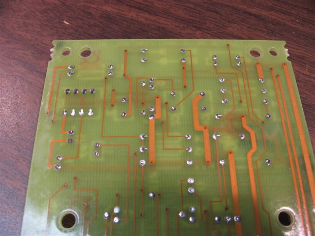
Back side of the board. This is a two layer board fortunately.
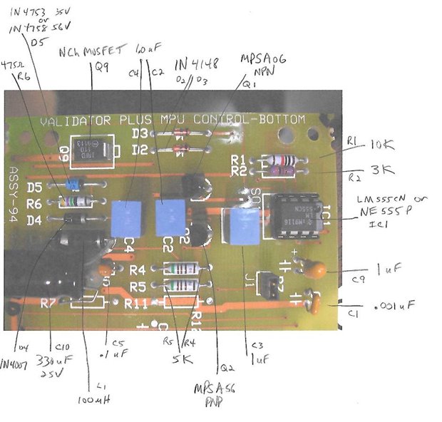
My first step to reverse engineering the circuit was to identify each of the components and to label a layout of the board. Fortunately I found that none of the components were OEM and that all were common and available in the shop parts supply. Where appropriate to understanding the circuit, Data Sheets were accessed. Here is the parts layout with labels.
The next step in the reverse engineering process is to create a schematic. This involves getting the component symbols on paper and determining their interconnections. For me this means a lot of time flipping the circuit board back and forth from front to back, visually tracing the the traces and vias, and using the ohm meter to verify connections. After a while, a rough draft of the schematic is produced by hand. A close inspection of the schematic and application of circuit logic often forces me back to the board to make sense of the circuit and to correct obvious gaps.
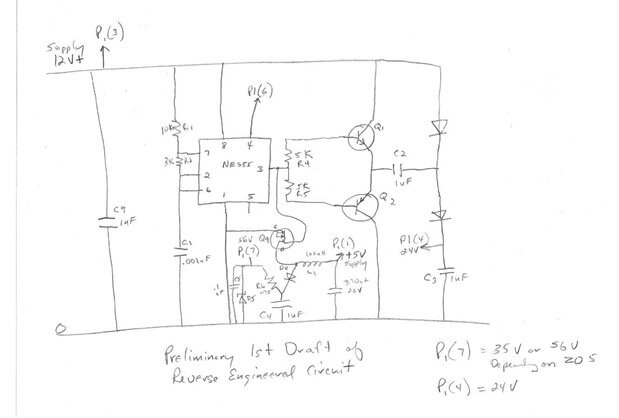
While it is possible to work off a crude schematic like this I always like to clean up the work and make a CAD schematic. Obviously, I got into a little trouble in the lower center of the hand produced schematic and we will clean up this section in the CAD production. Drawing freehand while reverse engineering a board usually leads to a messy first draft. Here is a CAD rendition.

With the schematic in hand it became clear that we actually had two converters on this board working off a single astable multivibrator. The 555 timer in this case is providing a 67 kHz 12 volt square wave. The section of the circuit that produces the 24 volt output uses this signal to drive a push pull set of NPN PNP general purpose transistors. The transistors in turn drive a voltage doubler with a 24 volt output. The 40 volt output is produce by driving an N Ch MOSFET with the 555 signal. The input voltage for this section is only 5 volts. When the MOSFET is in saturation energy is stored in the 100 uH inductor L1. When the MOSFET turns off this energy is released through diode D4 and stored in capacitor C4. Since the impedance is quite high the voltage is also quite high. Resistor R6 limits the current to Zener diode D5 which serves as a voltage regulator. Output in this case 40 volts is taken from the point in the circuit marked P1(7). C5 helps to decouple transients and noise from the output. C10 provides a reserve of current to L1 when the MOSFET turns on.
It is interesting to note that this design has been used by the sterilizer company for over a decade. When the board was first designed a 56 volt supply was needed and the requisite Zener diode was used to produce this voltage. As the technology of the OLEDs has improved the current required voltage became 35 volts and the only change to the circuit was the use of a 35 volt Zener. My rendition of the circuit creates 40 volts but this is only because my parts bins only had (2) 20 volt Zeners in this higher voltage range so I put them in series to approximate the actual circuit.
Now that we have the schematic the fun begins as we will bread board the circuit from the schematic to see if it will work as hoped. Here is a picture of the circuit bread boarded. Fortunately, except for the Zener, I had all the correct value components in the bins so I did not have to place an order.


For my initial test I have supplied +12 volts to the main rail and +5 volts to the MOSFET section of the circuit. I have an oscilloscope monitoring the output of the 555 astable multivibrator and I have DVMs on the 24 volt and 40 volt outputs. This is very unusual for me but it actually worked the first time. No Smoke, No Fire! Here are the outputs as displayed by the test instruments.
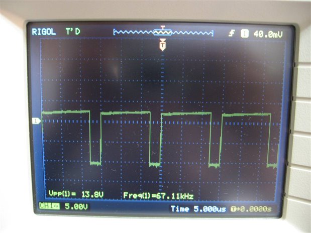
Sorry for the poor image. I was too lazy to export the image and just took a picture of it.
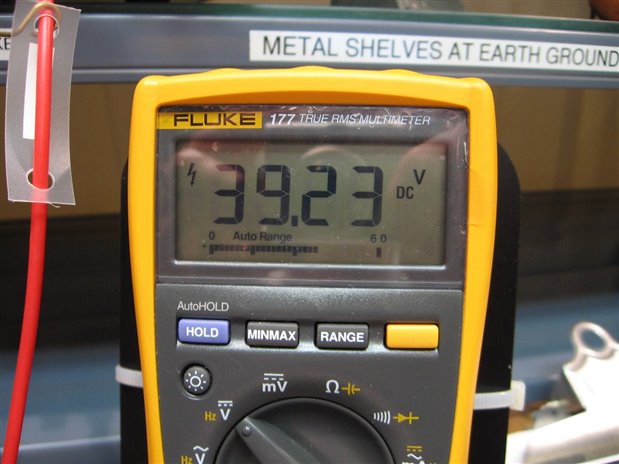
This is my 40 volt output point. Since I am using 2 Zeners in series and probably do not have them in their optimal operation mA range I feel the 39.23 V is acceptable.
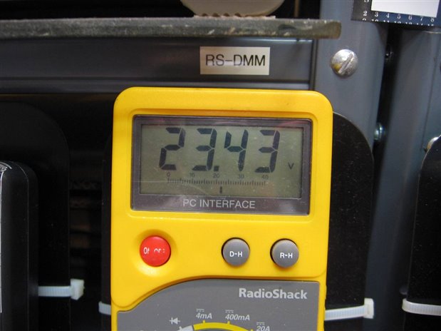
The regulation of this output is tied to the regulation of the 12 volt input of the circuit and I am very pleased with how close it came to 24 volts. The circuits that are using these voltage supplies are not precision and can tolerate a range of voltage.
The last thing that I did was to load the 40 volt circuit with a 10 K resistor and measured the voltage drop. The 10 K load produced a 2.39 Volt drop. Calculations indicated that the supply has an approximate 650 ohm ESR. At least 475 ohms of this ESR is the series current limiting resistor. I have left the test jig set up on the bench and will play with it for a couple days before tear down. I found this exercise helpful as I can see application of the concepts used in these 2 voltage converters will be useful in future designs.
John
Top Comments