

This blog is about my test rig for measuring DC-Dc converter efficiency in the range Vin/Vout 2-50V and Iin/Iout 1-10A. It can also be used to measure the power consumption of DC systems in same range.
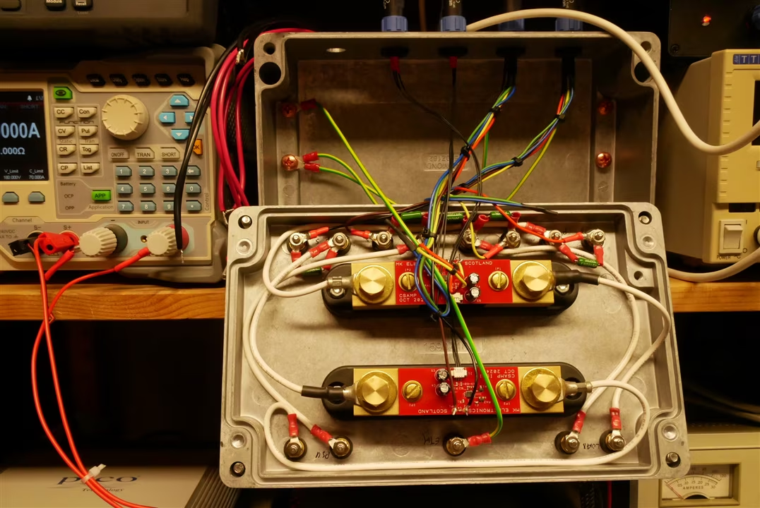
The test rig ready to run (power supply and device under test (DUT) not shown

Why bother to measure efficiency accurately?
First, the definition:
E = Pout/Pin
(Efficiency is the output power divided by the input power, always less than 1)
It’s more common to talk in terms of % efficiency (percentage):
E% = Pout/Pin * 100
In many cases there is no point in measuring it accurately or precisely.
(The distinction between the two is worth a blog of its own and you can find an adequate one here:
https://en.wikipedia.org/wiki/Accuracy_and_precision
)
If you are interested in how much money is being wasted in your converter, or how long a battery might last, it is very unlikely that you will care if the efficiency is 80% or 81%.
But there is a trend in DC-DC converter design (mainly in switching designs) to want to make the converter smaller. This in turn makes it much more difficult to dissipate heat in the converter. The space pressures are so extreme that in a design I have recently been working on a 2A 8V boost converter in a battery management system is crammed into a 3mm x 2mm surface mount package with a maximum power dissipation of 0.5W.
The converter chip must achieve better than 94% efficiency to avoid frying itself. In these cases it is often more helpful to look at the loss in the converter rather than the efficiency.
Loss = Pin – Pout
This is an example of subtracting one measurement from another and caring about the difference. As the efficiency improves then Pin and Pout become closer and must be measured more and more accurately to achieve the same proportional error in the loss measurement.
Considering a 95% efficient converter, the loss is 5% and if we are to measure the loss with only 5% error we need an accuracy in the loss measurement of 0.25%. This in turn requires that Pin and Pout should be measured with only 0.125% error.
Power can’t be directly measured but must be derived from measuring current and voltage and multiplying one by the other. So, we need to measure current and voltage with less than 0.0625% error over the full working range of the test rig.
Measuring Currents and Voltages
Ideally the uncertainty in the test instrument should be 10x less than that required for the measurement - so we are looking for an uncertainty of 0.00625% = 62ppm.
Let’s look for a DMM that can do this, at 1A and 10A (or 3A if it can’t do more)

This is not an exhaustive list but it illustrates that you can’t just go out and buy a DMM anywhere near accurate enough at measuring current to do the job.
An only one of them even offers a 10A range.
There are two ways we might measure the current that might be a bit cheaper.
Current Sensors
Farnell offer the LEM IN400-S at £1761 and offering 0.001% accuracy. Order code 3889271 if you want to play with one.
Its not quite ideal, being a 400A sensor (but I think LEM do lower current parts) and to an extent it shunts (pun intended) the problem down the road because it has a current output – so you’ll need a £5k plus DMM to read it.

Current Shunts
We don’t actually care very much about the absolute accuracy of the current measurement. What really matters is the ratio of the two currents. If we use two identical current shunts, one for input and one for output we can calibrate out any difference between them. We would like them to have the lowest possible temperature coefficient because they will not be working at the same current as each other all the time.
Bourns make a range of suitable current shunts and the RSN-10-100-B is available from Farnell (4540762) at a rather more reasonable £43.47 each.

I have a DAQ970 system with a solid state multiplexer and that can be used to measure the output of the current shunts as well as the input and output voltages.
(The output of the current shunt is to low to get the best out of the DAQ970 so I use them with amplifiers which are described later.)
Using the same instrument for all 4 measurements means that they all drift together as the instrument ages or changes temperature.
The basic voltage measuring performance of the DQ970 on the 1, 10 and 100V ranges is good enough to meet the requirements.
Test Rig Design details
The (simplified) circuit arrangement looks like this:

Note the use of Kelvin* connections to all 4 ports of the Device Under Test (DUT). The question will be answered later, but you can amuse yourself by guessing (or calculating) how long a piece of 16 SWG copper wire it takes to mess up the results. (assume 5V in, 5V out, and 5A).
*Explanation of Kelvin connections here:
https://en.wikipedia.org/wiki/Four-terminal_sensing
Hardware
The power supply I used is a TTi QL564TP. It has Ethernet or serial port remote control, and its two main channels can be paralleled to offer 4A at 50V or 8A at 25V. There are no special requirements for the power supply, apart from reasonably low noise and good short-term stability, since the measurements do not rely on it accuracy.
I used an electronic load for early experiments, and this is likely to be satisfactory in most cases. I also have a home made passive adjustable load (relays, big power resistors and fans) which I may try later.
Once again, the only important requirements for the load are reasonable short-term stability and low noise. Electronic loads must be used with care because they can interact with power supplies and can inject noise. In this application the power supply is likely to be under development and can’t be trusted to be well behaved. It’s worth checking for (lack of) oscillation on the DUT inputs and outputs.
I used a Rigol DL3031A which was almost satisfactory. Mine developed a 12mA offset during the development of this project and it was not possible to get it fixed or even calibrated in the UK. It would have had to be sent to Germany with a minimum cost of about £300. Rigol keep the details of the calibration commands secret, and I was unable to find them on the web. I decided to compensate for the offset in the control software and keep using it until it smokes. I have bought a new load from a different supplier for general use where to set current must agree with the real current.
The Bourns current shunts only produce 100mV @ 10A so I have made some x10 amplifiers to boost the signal to a more useful level. This does add a bit of complexity because the amplifiers must have isolated power supplies which can be floated to the maximum working voltage of the system (50V).

The amplifiers use Analog Devices ADA4523-1 op amps. These are zero drift parts with a maximum input offset drift of 10nV /C. Most of their other specs are pretty good too and they are OK with up to a 36V supply. I’m powering them with the little mains powered dual supplies described in this blog:
An isolated low noise +/-5V DC power supply
The amplifier design uses precision SOT23 resistor pairs to get best possible thermal drift of gain or offset.
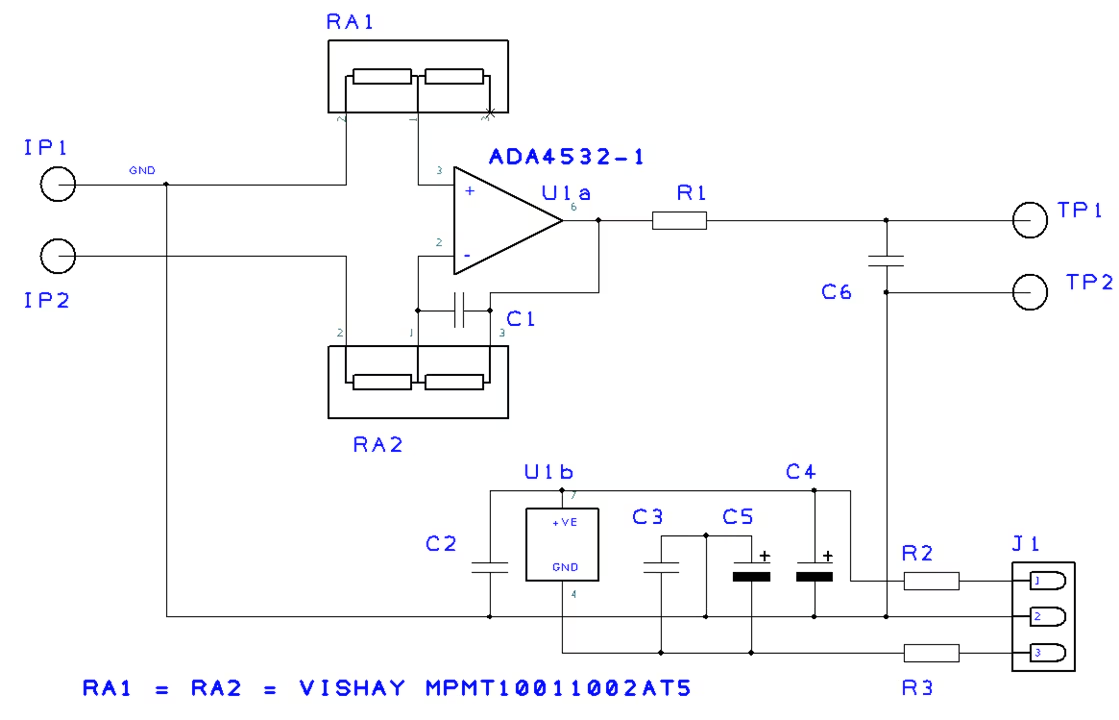
The RA1 resistor array is fitted to balance any thermal EMFs from RA2.
The resistor arrays contain 1 x 1k and 1 x 10k resistors so the gain of the amplifier is 10.
Inside view of the completed test box:
Software
The test rig has three remote controlled instruments, the TTi QL564TP, the Rigol DL3031A and the Keysight DAQ970. They all have Ethernet ports and all support LXi and SCPI to some extent.
In keeping with my usual practice, I don’t use LXi or VISA to talk to them but send SCPI commands directly to them using the Winsock interface in VB6. Even 25 years since Microsoft stopped supporting it, VB6 remains by far the best programming language and environment for quickly putting together a complete Windows GUI application.
The code allows you to set up sweeps of input voltage and load current, while observing and recording input and output current and voltage.
It also supports test and calibration.
I use some separate MATLAB code to process the data and make pretty graphs.
At some stage I shall add the ability to support temperature sweeping as well.
Sweeps are set up using config files like this:

Main window of the control prog:

Sweep Select and control window

Calibration
A good calibration of the rig is very difficult because it requires some very expensive test equipment (or a cunning trick that eludes me so far) so that the current shunts can be characterised over a range of currents and current ratios between the shunts.
The shunts have a very good temperature coefficient (about 0.02% over the temperature range from 20 to 70C) but they can also suffer from thermal EMFs generated in contacts and errors in the amplifiers.
A reasonable calibration can be done by linking the input to the output and testing the shunts at the same current. This is good for testing connecting cables.
The main control panel can be used to tune the two current shunts and their associated amplifiers for a perfect match at a single current.
Then the 100% efficient converter (100m of 16SWG copper wire) is attached, this was my first go:

The croc clip is holding the wires in place for the picture. The outer wires carry the current and the inner wires are the Kelvin sense wires.
The test run gave these results:

But the results were disappointing with the error rising to nearly 0.2% at 5V and 7A.
So I moved the sense wires to reduce the uncompensated length of the 16SWG copper link from a total of 127mm to 33m.

And the results improved:

Now the error at 5V and 7A is only 0.055% which I can live with for now !
NB This isn't a total calibration but it does give a good indication, other measurements were made !
Testing a converter
This is a converter based on the LT3780. I was doing some work to try and reduce the noise from it and made this test board with some filters. I won't discuss in detail because my upcoming Road Test of the SiC967 shows a much better way to filter the noise.

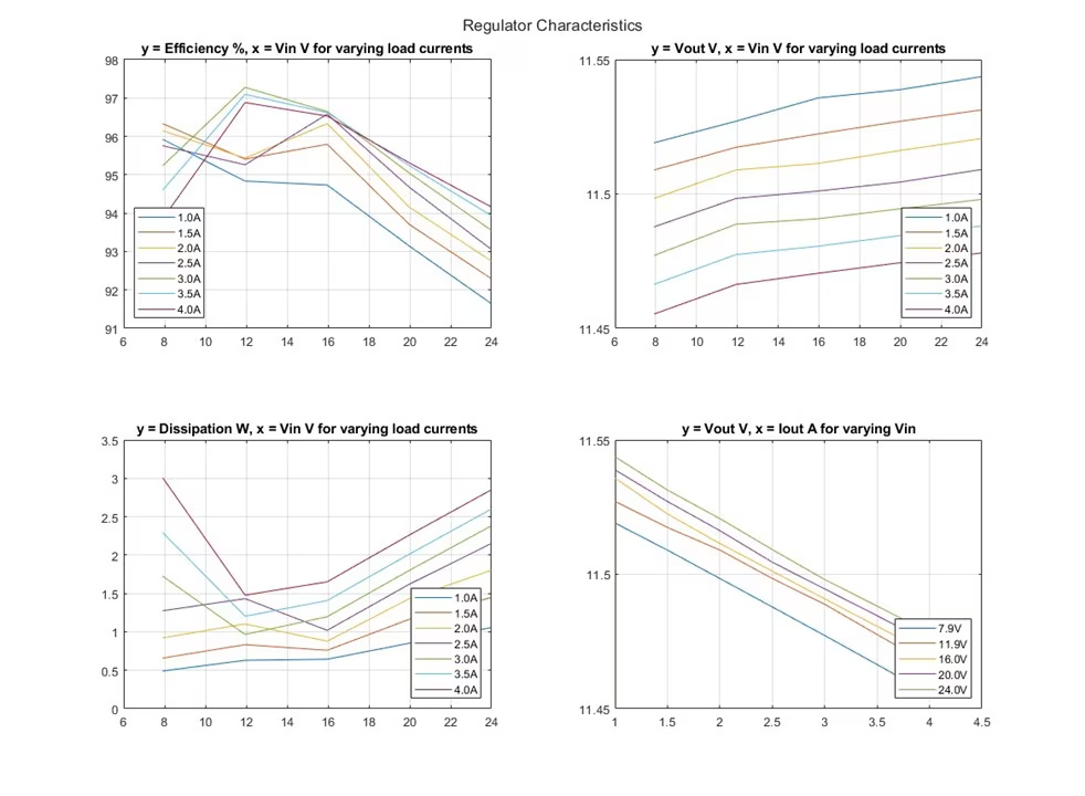
This is a SEPIC converter and it can produce nominally 12V on its output for any input from 6V to 24V. It was designed to power a test instrument which expected a 12V DC supply from a power brick, but was later required to work from a car 12V supply under all conditions including cranking. It's efficient and works as advertised but was very noisy. The filter made it less efficient, rather spoilt the load regulation and didn't make the noise all that much better. But you do get some interesting shapes in the efficiency graphs.
I tested my LT8640S based TO3 shaped 5V regulator described in this blog:
/members-area/personalblogs/b/michael-kellett-s-blog/posts/silent-switcher---lt8640s-meets-kicad

It runs out of steam a bit at 3A with only 5V input !

Summing Up
This test rig is still under development but so far it looks as if it will be worth the effort that went into making it.
It has enabled me to automate the process of testing power converters and at the same time ensures much greater consistency in the interconnections required.
I have used it in my Road Test of the Vishay SiC967 (not published yet) and on some internal projects as well.
I'll be happy to answer any questions and assist anyone attempting a similar construction.
Top Comments