element14 Community
element14 Community
    Register Log In
  • Site
  • Search
  • Log In Register
  • Community Hub
    Community Hub
    • What's New on element14
    • Feedback and Support
    • Benefits of Membership
    • Personal Blogs
    • Members Area
    • Achievement Levels
  • Learn
    Learn
    • Ask an Expert
    • eBooks
    • element14 presents
    • Learning Center
    • Tech Spotlight
    • STEM Academy
    • Webinars, Training and Events
    • Learning Groups
  • Technologies
    Technologies
    • 3D Printing
    • FPGA
    • Industrial Automation
    • Internet of Things
    • Power & Energy
    • Sensors
    • Technology Groups
  • Challenges & Projects
    Challenges & Projects
    • Design Challenges
    • element14 presents Projects
    • Project14
    • Arduino Projects
    • Raspberry Pi Projects
    • Project Groups
  • Products
    Products
    • Arduino
    • Avnet & Tria Boards Community
    • Dev Tools
    • Manufacturers
    • Multicomp Pro
    • Product Groups
    • Raspberry Pi
    • RoadTests & Reviews
  • About Us
  • Store
    Store
    • Visit Your Store
    • Choose another store...
      • Europe
      •  Austria (German)
      •  Belgium (Dutch, French)
      •  Bulgaria (Bulgarian)
      •  Czech Republic (Czech)
      •  Denmark (Danish)
      •  Estonia (Estonian)
      •  Finland (Finnish)
      •  France (French)
      •  Germany (German)
      •  Hungary (Hungarian)
      •  Ireland
      •  Israel
      •  Italy (Italian)
      •  Latvia (Latvian)
      •  
      •  Lithuania (Lithuanian)
      •  Netherlands (Dutch)
      •  Norway (Norwegian)
      •  Poland (Polish)
      •  Portugal (Portuguese)
      •  Romania (Romanian)
      •  Russia (Russian)
      •  Slovakia (Slovak)
      •  Slovenia (Slovenian)
      •  Spain (Spanish)
      •  Sweden (Swedish)
      •  Switzerland(German, French)
      •  Turkey (Turkish)
      •  United Kingdom
      • Asia Pacific
      •  Australia
      •  China
      •  Hong Kong
      •  India
      • Japan
      •  Korea (Korean)
      •  Malaysia
      •  New Zealand
      •  Philippines
      •  Singapore
      •  Taiwan
      •  Thailand (Thai)
      • Vietnam
      • Americas
      •  Brazil (Portuguese)
      •  Canada
      •  Mexico (Spanish)
      •  United States
      Can't find the country/region you're looking for? Visit our export site or find a local distributor.
  • Translate
  • Profile
  • Settings
Personal Blogs
  • Community Hub
  • More
Personal Blogs
Ralph Yamamoto's Blog Genmitsu CNC 3018-PRO - becoming useful
  • Blog
  • Documents
  • Mentions
  • Sub-Groups
  • Tags
  • More
  • Cancel
  • New
  • Share
  • More
  • Cancel
Group Actions
  • Group RSS
  • More
  • Cancel
Engagement
  • Author Author: ralphjy
  • Date Created: 9 Aug 2019 5:46 AM Date Created
  • Views 8280 views
  • Likes 9 likes
  • Comments 24 comments
  • genmitsu cnc 3018-pro
  • cnc router
Related
Recommended

Genmitsu CNC 3018-PRO - becoming useful

ralphjy
ralphjy
9 Aug 2019

I had a minor victory on my road to figuring out how to use my new CNC router.


I received the 0.5mm carbide end mills that I bought on Amazon and used one to successfully shorten a proto PCB that I need for my LoRaXes project.  The mill has about 4 mm of cutting depth.  The PCBs that I'm cutting are nominally around 1.6 mm thick.  Not a very impressive looking cutter but it worked.  I increased the spindle speed to 3000 RPM and reduced the feedrate to 80 mm/min and set the cutting depth to 0.15 mm per pass.


image


Here is the shortened PCB next to one that is uncut:

image


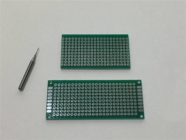
The cut edges are very smooth but you can see that they are not quite straight.  Not sure if I can improve that with tweaking or if that's the inherent limitation of an inexpensive router and cheap end mills.  Only time and experience will tell.  Anyway, I'm pretty satisfied with the outcome.  The tool did what I needed it to do. 

  • Sign in to reply

Top Comments

  • Fred27
    Fred27 over 6 years ago +5
    Welcome to the world of CNC. It's fun, isn't it? You may know this already, but PCBs are particularly may to cut. They will blunt your endmills and the dusty is abrasive and nasty. For that particular…
  • Fred27
    Fred27 over 6 years ago +4
    I originally got a CNC mill (well, converted a mill myself) in order to mill PCBs. I ended up moving to etching as milling anything smaller than SOIC starts to get impractical. https://0xfred.wordpress…
  • balearicdynamics
    balearicdynamics over 6 years ago in reply to ralphjy +3
    The laser is controlled by PWM and there is a lot of relatively low power spindle and small diameter. The z-axis is not easy to be adapted (maybe with some 3D printed adjustment. The software I use is…
Parents
  • balearicdynamics
    balearicdynamics over 6 years ago

    Welcome on the CNC world image Do you plan to use it for PCB only or also something else? What kind of model? Some photos? If you need help, just ask.


    BTW... Maybe it is worth to open a group on CNC milling techniques, eventually finalized to the electronic design and prototyping support?


    Enrico

    • Cancel
    • Vote Up +2 Vote Down
    • Sign in to reply
    • More
    • Cancel
  • ralphjy
    ralphjy over 6 years ago in reply to balearicdynamics

    Hi Enrico,


    I did a blog post earlier when I first assembled this printer: Genmitsu CNC 3018-PRO


    I got the CNC mill to help with my electronic projects, so I'm hoping to also use it for things like small panels or face plates made out of plastic, acrylic, wood, or aluminum.  Hopefully will improve the quality and appearance of my builds.  There is also a low power (5.5W) laser module available that could be used for engraving (not sure if that is enough power to cleanly cut wood or acrylic).


    SainSmart is supposed to have a very active support community for their CNC products, but it's on Facebook and I really dislike Facebook.


    I'd support a group on Element14 if others would also like to start one.


    Ralph

    • Cancel
    • Vote Up +2 Vote Down
    • Sign in to reply
    • More
    • Cancel
  • balearicdynamics
    balearicdynamics over 6 years ago in reply to ralphjy

    The laser is controlled by PWM and there is a lot of relatively low power spindle and small diameter. The z-axis is not easy to be adapted (maybe with some 3D printed adjustment. The software I use is the T2 Laser by Zac. This guy (I also interviewed him for a series of tips on laser cutting and engraving for a series I am publishing on a magazine) and his software works fine with the z-axis in positive and negative. I mean: when you laser cut, z-axis should start from highest value and goes down decreasing instead while you are engraving or milling, z-axis starts from zero and goes to negative values, at least by convention but, as a matter of fact, you can set up the vertical path as you prefer.


    His program works with GRBL (and is possible to update the GRBL firmware on an Arduino using his software too. The software supports the milling settings too, where it is expected that the g-code for the milling has come different parameters like speed instead of laser intensity.


    I have already found on Amazon several spindles sold (not super cheap but should be super precise so the price is correct) together with the motor controller as well as the Aluminium support that as I mentioned above it is not difficult to adapt to the z-axis. I have already modified one of the z-axis to support the laser I am using that is 7W and considerably bigger than the standard 2,5W max sold with the Eleks laser (I will use the structure of this laser engraver as I have already assembled and used three models of different sizes and it seems stable (laser needs also a high precision and repeatability.


    Instead about the board, it is not difficult to replace the signals of the actual board (It is Mana 2 SE) to manage the spindle with the speed controlled via PWM instead of the laser. You are also right about the power of the spindle (the one in the link example is about 4KW) but as well as the laser, excluding the PWM speed controlled by a logic signal, the power of the tool is independent. So probably this may not be a serious issue.


    Frankly, I prefer the program MACH 3 I use on the big CNC machine but the problem is that this software runs only with the parallel interface while the advantage of the T2 Laser is that it runs on USB.


    This is the actual scenario, I think that soon I will buy the spindle and start making tests to see what is preferable but I see hard to manage a parallel interface. I become crazy to set up a dedicated desktop Windows computer supporting the standard Parallel interface on the board. And – before you ask– the USB to parallel adapter is not accepted and the parallel won't work. This is the first thing I tried when I have assembled the other device.


    Enrico

    • Cancel
    • Vote Up +3 Vote Down
    • Sign in to reply
    • More
    • Cancel
  • shabaz
    shabaz over 6 years ago in reply to balearicdynamics

    Hi Enrico,


    There's another approach, that could be worth exploring. I too started to explore it last Xmas time, but have not progressed so much yet : (

    It concerns using BBB for the CNC controller. There is existing software for this, however the control board is not really open source : ( There's a firm selling the board, but it cost $100 or so from memory.

    So, I was trying to figure it out from the old schematic for it (a bit like the raspberry pi, an older schematic was available) what the connections to the BBB are, so that there can be an open source PCB that anyone can make, to plug on the BBB.

    I managed to map out the pins, but I still have to design the interface board to the stepper driver modules. Also, some legacy-type boards appear to need a lot of wiring, or need expensive DB9 type connections, I hoped to eliminate it mostly, using Ethernet or phone-like cables (not for the power, just for the control), from the interface board to the stepper drives (and have a little adapter PCB at the stepper drive end, for the least amount of wiring possible). I'd not figured out what connector to use for power, ideally something with ready-made cables, to reduce wiring effort with power too.

    • Cancel
    • Vote Up +3 Vote Down
    • Sign in to reply
    • More
    • Cancel
  • balearicdynamics
    balearicdynamics over 6 years ago in reply to shabaz

    Sounds interesting, Shabaz. I know that the BBB is better than ever for this kind of applications. And here I have a couple of them, one with the WiFi onboard and one without. And the LinuxCNC shows good explanations on this device. But I know LinuxCNC and when I tested it it was light-years far from the Mach 3 software. About the connectors using the Rj45 for Ethernet is a great solution I already saw in other professional CNC for cheaper and reliable connectors.


    I am still in the evaluation of the possibilities phase so this can be considered, you are right. What kind of board it is what you mention?


    Enrico

    • Cancel
    • Vote Up +1 Vote Down
    • Sign in to reply
    • More
    • Cancel
  • shabaz
    shabaz over 6 years ago in reply to balearicdynamics

    Hi Enrico,


    The existing boards are listed here, but most of them are paid options. I wouldn't mind paying if they looked like they really met my needs, but with all the effort tailoring them, and wiring them, I hope it will be easier to just design a custom board. I tried thinking what I would like if I had a choice, and decided to have a larger board than BBB, so BBB becomes the daughter board, and an edge connection method for expansion if needed (i.e. with a separate backplane board) although it should work standalone. Also the connectors with ready-made cables, to reduce cable assembly.

    I'll try to sketch some system design, maybe we can turn it into some implementation if it looks worthwhile. I don't really know the quality compared to Mach 3, so that is another factor to consider as you say.

    • Cancel
    • Vote Up +2 Vote Down
    • Sign in to reply
    • More
    • Cancel
  • balearicdynamics
    balearicdynamics over 6 years ago in reply to shabaz

    If we don't try, we can't know. And at the end of the project sure we have a better knowledge than before. And I am almost sure that the machine will work.

    • Cancel
    • Vote Up +2 Vote Down
    • Sign in to reply
    • More
    • Cancel
Comment
  • balearicdynamics
    balearicdynamics over 6 years ago in reply to shabaz

    If we don't try, we can't know. And at the end of the project sure we have a better knowledge than before. And I am almost sure that the machine will work.

    • Cancel
    • Vote Up +2 Vote Down
    • Sign in to reply
    • More
    • Cancel
Children
  • shabaz
    shabaz over 6 years ago in reply to balearicdynamics

    Hi Enrico (and everyone),

    Here's some ideas, it would be interesting to know what you think, maybe the idea isn't feasible or there are better ways. Also, I don't know what features/connectors are useful.

    I'm currently thinking maybe have an "Interface board" that can connect to external drivers in scenario 1, but can use small stepper PCBs (some off-the-shelf one, to be determined) in scenario 2.

    For scenario 1, the configuration jumpers direct the BBB pins (via buffers) to the RJ45 sockets (are 4 enough?).

    image

    For scenario 2, the jumpers are placed so that the BBB pins for the drivers are routed through the edge connector instead, like a pass-through.

    This way, the same RJ45 can be used for direct motor control in scenario 2. It would result in a low-cost stepper driver carrier board that could be swapped out for a new design if low-cost stepper driver boards need upgrading to more powerful ones. It could be a new open interface : ) so anyone can design carrier boards for their favourite stepper driver chips/boards.


    image

    I can't think what connectors could be useful for power.. maybe RJ45 again, but with 4 wires for ground, and 4 for positive. Not sure! All ideas welcome, this is just a concept, and I'm not very knowledgeable in this.

    • Cancel
    • Vote Up +3 Vote Down
    • Sign in to reply
    • More
    • Cancel
  • genebren
    genebren over 6 years ago in reply to shabaz

    shabaz,


    This looks pretty good.  I am wondering if this is going a little too far off of topic on Ralph's post?  Maybe we should take this conversation into it's own thread?


    Gene

    • Cancel
    • Vote Up +1 Vote Down
    • Sign in to reply
    • More
    • Cancel
  • balearicdynamics
    balearicdynamics over 6 years ago in reply to shabaz

    Hi Shabaz,


    In my opinion, the scenario 2 should be excluded, while the scenario 1 is perfect. I try to explain my point of view:


    As a matter of fact, independently by what is the real power of the stepper motors (and the spindle), the logic should always be separated by the power stage. At least for two reasons: one is to avoid any kind of electric and electronic risk, the other is to have the same logic able to control any kind of motor. That is the scenario 1.


    The same signal sequence (A- B- A+ B+ on a bipolar stepper) will generate a step in one direction, in another direction or stopped but not freed. Then if you have a small 1A max stepper you can use half-bridges like ULN2003 or 2004  if the power is under 2.5A (peak). If you should control up to 5A (if I am not wrong) you can use an L298 like those stepper motor controllers yo find almost everywhere for 5$ or less.


    With high power motors (over 10A) you should use a more powerful motor controller, possibly that has its own high power logic able for example to manage microstepping and so on.


    For Nema17 (those you find in the 3D printers, the home laser engraver, etc.) a small half-bridge is sufficient. To make my The Lino Project with Arduino Mega 2560: Interrupts and Motors I had to use high torque stepper motors so I used a Moon's high power stepper motor (it costs about 60$); as you can see in the images, in the high power session (that should reside in the moving engine) wires are 1mm and can be also bigger if the power is higher. But also the logic level can control these.


    On the logic side instead, the same board, as you suggest in scenario 1, can control with the same efficiency and precision the stepper of the head of a CD driver as well as one of those motors.


    The connections between the logic and the power session (the drivers and motors) can be done as you prefer, possibly with a cheap solution. My RS3020 (Chinese optimization) for example uses multi-cable like those for the printers and a screwed Philips connector. And it works for years.


    Similar is the case of the spindle or, generically, high power and high speed (30.000 RPM and more) DC motors. These are connected to an inverter. A sort of PWM to PWM interface you can program on how much power you should send to the motor at a certain frequency and what speed (expressed in inverter frequency) the motor should run respect to the PWM of the logic board. And other parameters too. But the principle of separating the power stage is respected as well.

    • Cancel
    • Vote Up +2 Vote Down
    • Sign in to reply
    • More
    • Cancel
  • shabaz
    shabaz over 6 years ago in reply to balearicdynamics

    Hi Enrico,


    Thanks for the valuable information, this is really helpful. Also, I'd forgotten about the spindle motor : (

    Let's start a topic somewhere (called "CNC interface board ideas" or something) and we can continue there. It's great to be thinking the concept as we are, between us all first, so we can have a useful design.

    • Cancel
    • Vote Up +3 Vote Down
    • Sign in to reply
    • More
    • Cancel
  • balearicdynamics
    balearicdynamics over 6 years ago in reply to shabaz

    Good idea Shabaz!


    Enrico

    • Cancel
    • Vote Up +2 Vote Down
    • Sign in to reply
    • More
    • Cancel
element14 Community

element14 is the first online community specifically for engineers. Connect with your peers and get expert answers to your questions.

  • Members
  • Learn
  • Technologies
  • Challenges & Projects
  • Products
  • Store
  • About Us
  • Feedback & Support
  • FAQs
  • Terms of Use
  • Privacy Policy
  • Legal and Copyright Notices
  • Sitemap
  • Cookies

An Avnet Company © 2025 Premier Farnell Limited. All Rights Reserved.

Premier Farnell Ltd, registered in England and Wales (no 00876412), registered office: Farnell House, Forge Lane, Leeds LS12 2NE.

ICP 备案号 10220084.

Follow element14

  • X
  • Facebook
  • linkedin
  • YouTube