element14 Community
element14 Community
    Register Log In
  • Site
  • Search
  • Log In Register
  • About Us
  • Community Hub
    Community Hub
    • What's New on element14
    • Feedback and Support
    • Benefits of Membership
    • Personal Blogs
    • Members Area
    • Achievement Levels
  • Learn
    Learn
    • Ask an Expert
    • eBooks
    • element14 presents
    • Learning Center
    • Tech Spotlight
    • STEM Academy
    • Webinars, Training and Events
    • Learning Groups
  • Technologies
    Technologies
    • 3D Printing
    • FPGA
    • Industrial Automation
    • Internet of Things
    • Power & Energy
    • Sensors
    • Technology Groups
  • Challenges & Projects
    Challenges & Projects
    • Design Challenges
    • element14 presents Projects
    • Project14
    • Arduino Projects
    • Raspberry Pi Projects
    • Project Groups
  • Products
    Products
    • Arduino
    • Avnet Boards Community
    • Dev Tools
    • Manufacturers
    • Multicomp Pro
    • Product Groups
    • Raspberry Pi
    • RoadTests & Reviews
  • Store
    Store
    • Visit Your Store
    • Choose another store...
      • Europe
      •  Austria (German)
      •  Belgium (Dutch, French)
      •  Bulgaria (Bulgarian)
      •  Czech Republic (Czech)
      •  Denmark (Danish)
      •  Estonia (Estonian)
      •  Finland (Finnish)
      •  France (French)
      •  Germany (German)
      •  Hungary (Hungarian)
      •  Ireland
      •  Israel
      •  Italy (Italian)
      •  Latvia (Latvian)
      •  
      •  Lithuania (Lithuanian)
      •  Netherlands (Dutch)
      •  Norway (Norwegian)
      •  Poland (Polish)
      •  Portugal (Portuguese)
      •  Romania (Romanian)
      •  Russia (Russian)
      •  Slovakia (Slovak)
      •  Slovenia (Slovenian)
      •  Spain (Spanish)
      •  Sweden (Swedish)
      •  Switzerland(German, French)
      •  Turkey (Turkish)
      •  United Kingdom
      • Asia Pacific
      •  Australia
      •  China
      •  Hong Kong
      •  India
      •  Korea (Korean)
      •  Malaysia
      •  New Zealand
      •  Philippines
      •  Singapore
      •  Taiwan
      •  Thailand (Thai)
      • Americas
      •  Brazil (Portuguese)
      •  Canada
      •  Mexico (Spanish)
      •  United States
      Can't find the country/region you're looking for? Visit our export site or find a local distributor.
  • Translate
  • Profile
  • Settings
Arduino
  • Products
  • More
Arduino
Arduino Forum abut arduino
  • Blog
  • Forum
  • Documents
  • Quiz
  • Events
  • Polls
  • Files
  • Members
  • Mentions
  • Sub-Groups
  • Tags
  • More
  • Cancel
  • New
Join Arduino to participate - click to join for free!
Actions
  • Share
  • More
  • Cancel
Forum Thread Details
  • State Not Answered
  • Replies 12 replies
  • Subscribers 394 subscribers
  • Views 814 views
  • Users 0 members are here
Related

abut arduino

Former Member
Former Member over 9 years ago

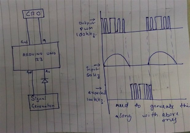
a sine wave is applied at a0 using a diode,so that it geets rectified and then after pwm the square obatIned is only with wrt positive cycle ,i need to generate pwm  even during negative cycle and one way is to do it by full bridge rectifier .so is there any way by arduino coding i could get it

  • Sign in to reply
  • Cancel

Top Replies

  • clem57
    clem57 over 9 years ago +1
    Yes just measure both positive and negative values during entire cycle.
  • Robert Peter Oakes
    Robert Peter Oakes over 9 years ago +1
    How about offset the sine wave to 50% of VRef (Capacitor coupled will do it, and a divider network), then simply read the whole waveform as a positive value this way 0V = 511 decimal from ADC, -2.5V will…
  • michaelkellett
    0 michaelkellett over 9 years ago

    Are you trying to generate pulses of controlled width, one per half cycle of an incoming sine wave ?


    If so then please tell us the frequency of the input sine wave, the range of pulse widths you need coming out, where the sine wave comes from and what hardware you have. Some diagrams would be nice. With some additional information it will be possible to help you. If my guess at what you are trying to do is correct it is possible in principle.


    MK

    • Cancel
    • Vote Up 0 Vote Down
    • Sign in to reply
    • Verify Answer
    • Cancel
  • clem57
    0 clem57 over 9 years ago

    Yes just measure both positive and negative values during entire cycle.

    • Cancel
    • Vote Up +1 Vote Down
    • Sign in to reply
    • Verify Answer
    • Cancel
  • amgalbu
    0 amgalbu over 9 years ago

    Hi

    you could measure the time between two "zero crossings". That's the period of the PWM signal. During the negative part of the sine waveform, use a timer to drive PWM output


    Cheers

    Ambrogio

    • Cancel
    • Vote Up 0 Vote Down
    • Sign in to reply
    • Verify Answer
    • Cancel
  • Robert Peter Oakes
    0 Robert Peter Oakes over 9 years ago

    How about offset the sine wave to 50% of VRef (Capacitor coupled will do it, and a divider network), then simply read the whole waveform as a positive value


    this way 0V = 511 decimal from ADC, -2.5V will be 0 decimal and +2.5V will be 1023


    this assumes the input sine wave is appropriatly scaled to a +-2.5V max signal


    All the questions Mike asked are still valid though, please provide


    You also have not said what resolution you desire to read the values, I am assuming 10 bit based on the built in ADC of the arduino and with my proposed solution, you will have 9 bits in each direction (Simple assume the MSB is a sign bit

    • Cancel
    • Vote Up +1 Vote Down
    • Sign in to reply
    • Verify Answer
    • Cancel
  • clem57
    0 clem57 over 9 years ago in reply to Robert Peter Oakes

    Peter Oakes & Michael Kellett

    are correct asking for more information as stated.. Also oversample twice the frequency you plan for better accuracy is highly recommended.

    Clem

    • Cancel
    • Vote Up 0 Vote Down
    • Sign in to reply
    • Verify Answer
    • Cancel
  • peterjcs23
    0 peterjcs23 over 9 years ago

    do you have a problem with using a full-wave rectifier as that sounds like your best bet?

    • Cancel
    • Vote Up 0 Vote Down
    • Sign in to reply
    • Verify Answer
    • Cancel
  • Former Member
    0 Former Member over 9 years ago in reply to michaelkellett

    #include<PWM.h>

    int32_t frequency =100000;

    void setup()

    {

    InitTimersSafe() ;

    bool success = SetPinFrequencySafe(9, frequency);

    if(success) {

      pinMode(13, OUTPUT);

      digitalWrite(13,HIGH);

    }

    }


    void loop() {

    int sensorValue= analogRead(A0);

    pwmWrite(9, sensorValue /4);

    delay(30);


    }


                                                                                              from the signal generator i have  provide a supply of  5 v pp and 50 hz frequency, +ve part provided to the  diode and the diode is connected to the  a0 pin in the arduino uno  and-ve part of signal generator to ground the .then is have taken output from 9 pin and at this point i am getting pwm of  only +ve cycle of sine wave input as reference(as i have used a diode)image

    now i need to generate pwm of -ve cycle

    1. i want arduino code to store the +ve cycle pwm wave  in other pin and then during -ve cycle i want to output it through this pin .by this i would get  pwm for both +ve and -ve cycle of sine wave  and  it would be helpful if any way is there to distinguish the pwm for +ve and -ve cycle

    2 in a simple way i need to generate a pwm for -ve cycle and need to do it by arduino code only and not by rectifier (less circuit part  and more part must be done in coding)

    any way u could help me to do this it would be of great help. image

    • Cancel
    • Vote Up 0 Vote Down
    • Sign in to reply
    • Verify Answer
    • Cancel
  • Former Member
    0 Former Member over 9 years ago in reply to clem57

    We need to send same values of PWM to negative cycle. If we measure negative supply, output will be zero as diode blocks negative supply. We need to send psuedo values to negative cycle.

    • Cancel
    • Vote Up 0 Vote Down
    • Sign in to reply
    • Verify Answer
    • Cancel
  • Former Member
    0 Former Member over 9 years ago in reply to amgalbu

    can u tell me the code for that

    • Cancel
    • Vote Up 0 Vote Down
    • Sign in to reply
    • Verify Answer
    • Cancel
  • Former Member
    0 Former Member over 9 years ago in reply to peterjcs23

    now we just thought its better to use codes than more diodes ,just much simpler way of codes of arduino

    • Cancel
    • Vote Up 0 Vote Down
    • Sign in to reply
    • Verify Answer
    • Cancel
>
element14 Community

element14 is the first online community specifically for engineers. Connect with your peers and get expert answers to your questions.

  • Members
  • Learn
  • Technologies
  • Challenges & Projects
  • Products
  • Store
  • About Us
  • Feedback & Support
  • FAQs
  • Terms of Use
  • Privacy Policy
  • Legal and Copyright Notices
  • Sitemap
  • Cookies

An Avnet Company © 2025 Premier Farnell Limited. All Rights Reserved.

Premier Farnell Ltd, registered in England and Wales (no 00876412), registered office: Farnell House, Forge Lane, Leeds LS12 2NE.

ICP 备案号 10220084.

Follow element14

  • X
  • Facebook
  • linkedin
  • YouTube