element14 Community
element14 Community
    Register Log In
  • Site
  • Search
  • Log In Register
  • About Us
  • Community Hub
    Community Hub
    • What's New on element14
    • Feedback and Support
    • Benefits of Membership
    • Personal Blogs
    • Members Area
    • Achievement Levels
  • Learn
    Learn
    • Ask an Expert
    • eBooks
    • element14 presents
    • Learning Center
    • Tech Spotlight
    • STEM Academy
    • Webinars, Training and Events
    • Learning Groups
  • Technologies
    Technologies
    • 3D Printing
    • FPGA
    • Industrial Automation
    • Internet of Things
    • Power & Energy
    • Sensors
    • Technology Groups
  • Challenges & Projects
    Challenges & Projects
    • Design Challenges
    • element14 presents Projects
    • Project14
    • Arduino Projects
    • Raspberry Pi Projects
    • Project Groups
  • Products
    Products
    • Arduino
    • Avnet Boards Community
    • Dev Tools
    • Manufacturers
    • Multicomp Pro
    • Product Groups
    • Raspberry Pi
    • RoadTests & Reviews
  • Store
    Store
    • Visit Your Store
    • Choose another store...
      • Europe
      •  Austria (German)
      •  Belgium (Dutch, French)
      •  Bulgaria (Bulgarian)
      •  Czech Republic (Czech)
      •  Denmark (Danish)
      •  Estonia (Estonian)
      •  Finland (Finnish)
      •  France (French)
      •  Germany (German)
      •  Hungary (Hungarian)
      •  Ireland
      •  Israel
      •  Italy (Italian)
      •  Latvia (Latvian)
      •  
      •  Lithuania (Lithuanian)
      •  Netherlands (Dutch)
      •  Norway (Norwegian)
      •  Poland (Polish)
      •  Portugal (Portuguese)
      •  Romania (Romanian)
      •  Russia (Russian)
      •  Slovakia (Slovak)
      •  Slovenia (Slovenian)
      •  Spain (Spanish)
      •  Sweden (Swedish)
      •  Switzerland(German, French)
      •  Turkey (Turkish)
      •  United Kingdom
      • Asia Pacific
      •  Australia
      •  China
      •  Hong Kong
      •  India
      •  Korea (Korean)
      •  Malaysia
      •  New Zealand
      •  Philippines
      •  Singapore
      •  Taiwan
      •  Thailand (Thai)
      • Americas
      •  Brazil (Portuguese)
      •  Canada
      •  Mexico (Spanish)
      •  United States
      Can't find the country/region you're looking for? Visit our export site or find a local distributor.
  • Translate
  • Profile
  • Settings
Arduino
  • Products
  • More
Arduino
Arduino Forum Data output from OV7670
  • Blog
  • Forum
  • Documents
  • Quiz
  • Events
  • Polls
  • Files
  • Members
  • Mentions
  • Sub-Groups
  • Tags
  • More
  • Cancel
  • New
Join Arduino to participate - click to join for free!
Actions
  • Share
  • More
  • Cancel
Forum Thread Details
  • State Not Answered
  • Replies 13 replies
  • Subscribers 392 subscribers
  • Views 2243 views
  • Users 0 members are here
Related

Data output from OV7670

Former Member
Former Member over 9 years ago

Hi All.


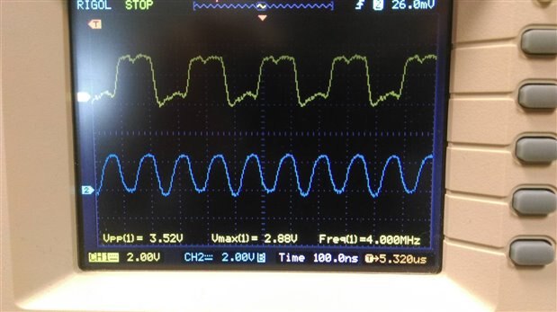
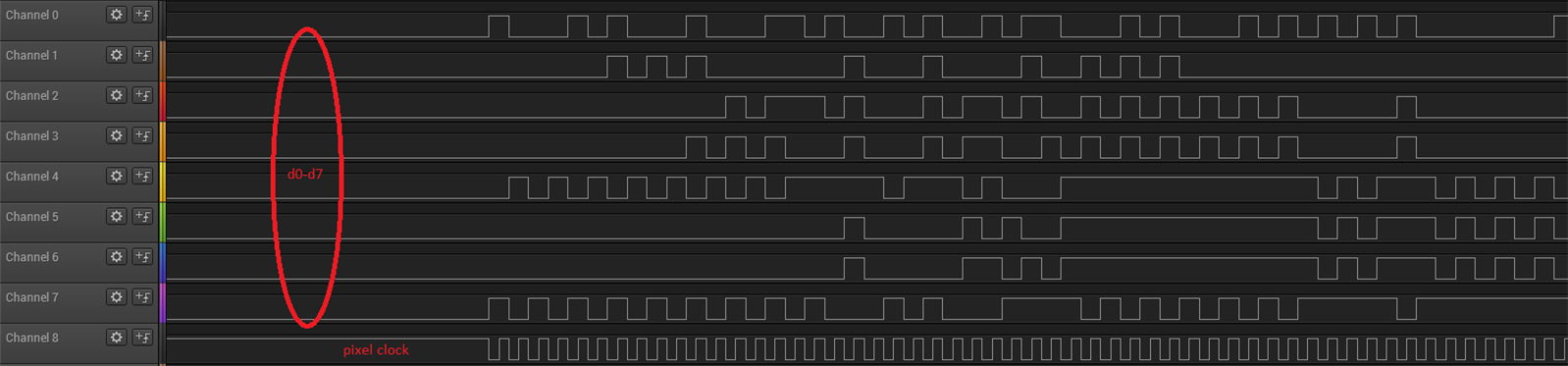
I have been trying to get some useful data from the OV7670 camera module but it seems that it is not outputting the correct data. I have been using this code: https://github.com/ComputerNerd/ov7670-no-ram-arduino-uno and everything seems fine from a software point of view but what I am getting out is not as expected. With the lens covered I should get a stream of repetitive data like [0,80,0,80,0,80....] but I dont regardless of whether it is covered or not. I have tried various register settings and still no joy. Even with default register settings I should be able to see a basic image. I have also viewed the data from the device on a logic analyzer and it is clear that the data is random. The pic below is the camera module output data with the lens covered and it can be seen that the data is totally random.


image


Anyone know why this is happening or has seen it before?


Thanks,


Mark.

  • Sign in to reply
  • Cancel

Top Replies

  • clem57
    clem57 over 9 years ago +1
    9 times out of 10, the connections are not right. Please double check these: Connections Order Arduino ov7670 A5->SIOC A4<->SIOD Note what I have just described (above) are I2C connections you will need…
  • Former Member
    Former Member over 9 years ago in reply to shabaz +1
    Below is a capture from the oscilloscope. Blue is the pixel clock and yellow is one of the data pins. I was clocking the logic analyzer using a trigger from inside my code when the HREF went high. As you…
  • clem57
    0 clem57 over 9 years ago

    9 times out of 10, the connections are not right. Please double check these:

    Connections

    Order Arduino ov7670

    A5->SIOC

    A4<->SIOD

    Note what I have just described (above) are I2C connections you will need pullup resistors to 3.3v for both SIOC and SIOD.

    You must not connect the resistors to 5v.

    I have found that certain resistor values do not work such as 1K and 2.2K but found 4.7K and 10K to work.

    11-> (convert 5v to 3.3v) XCLK

    A0<-0

    A1<-1

    A2<-2

    A3<-3

    4<-4

    5<-5

    6<-6

    7<-7

    3<-VSYNC

    2<-PCLK

    GND->PWDN

    3.3->RESET

    GND->GND

    3.3v->3.3v

    Do you have a way to check all the voltage levels?

    Clem

    PS check the address of I2C is correct also.

    • Cancel
    • Vote Up +1 Vote Down
    • Sign in to reply
    • Verify Answer
    • Cancel
  • shabaz
    0 shabaz over 9 years ago

    Also, as well as the checks clem57 has mentioned, I'd strongly advise connecting up an oscilloscope (not logic analyser)

    to at least a few of the connections, to see the waveform shape. There could be all sorts of issues.

    It is also not an ideal project to follow because it is operating outside of the specs slightly (the OV7670 is designed for 3V max).

    Also, wire lengths will matter, and maybe even a buffer is needed.


    See here for a project that used a different OmniVision part, (and doesn't use the Arduino) but probably you can glean some tips from it:

    BBB - Imaging with a PRU connected Camera

    If it is an ebay type camera board, examine it and make sure they didn't shortcut like using poor choice of decoupling capacitors.

    It is critical with these cameras.

    If you're using the Uno, to be honest it may be better to find an alternative way of using imaging (e.g. Pi 3 and associated camera)

    because the Arduino Uno is lacking in resources : (

    • Cancel
    • Vote Up 0 Vote Down
    • Sign in to reply
    • Verify Answer
    • Cancel
  • Former Member
    0 Former Member over 9 years ago in reply to shabaz

    The voltage levels are all correct, I have checked with scope and meter. I have also checked various registers via I2C and they seem ok. The device is spitting out data upon power up with the given clock and so would suggest that wiring configuration is ok. This project has been undertaken a lot with arduinos with success so I would say that the voltages and speeds are ok.


    At this moment I would just be happy to see the correct data coming from the device, whether I use a scope or logic analyzer. I am not to concerned with data storage and transmission or MCU at the moment. With the correct voltages and clock I should output image data but for some reason it dosn't.

    • Cancel
    • Vote Up 0 Vote Down
    • Sign in to reply
    • Verify Answer
    • Cancel
  • shabaz
    0 shabaz over 9 years ago in reply to Former Member

    What did the waveforms look like on the scope? Any noise or glitches on the oscilloscope analog traces?

    Do you have a screen grab from oscilloscope analog traces (not logic traces).

    How was your logic analyser configured? Clocking on the pixel clock, or free-running capture from the logic analyzer's own clock?

    Also a photo of the setup would help.

    • Cancel
    • Vote Up 0 Vote Down
    • Sign in to reply
    • Verify Answer
    • Cancel
  • shabaz
    0 shabaz over 9 years ago in reply to Former Member

    Also, is it an assumption that the data is random, or have you checked?

    i.e. can you plot it in a graphic view (an entire frame if possible), to see if there is any signal in the noise?

    It doesn't look entirely random to me. I can see the most significant bits alternated on every other byte for the first 16 bytes. It is to be expected for the least significant ones to possibly have variations due to sensor noise.

    I don't know what format is expected, but it doesn't appear random.

    • Cancel
    • Vote Up 0 Vote Down
    • Sign in to reply
    • Verify Answer
    • Cancel
  • Former Member
    0 Former Member over 9 years ago in reply to shabaz

    Below is a capture from the oscilloscope. Blue is the pixel clock and yellow is one of the data pins. I was clocking the logic analyzer using a trigger from inside my code when the HREF went high.


    image


    As you say the MSB alternates to begin with but the rest seem to be way to random. For a 2 byte pixel for a black image they should repeat every 2 bytes but clearly doesn't.

    • Cancel
    • Vote Up +1 Vote Down
    • Sign in to reply
    • Verify Answer
    • Cancel
  • shabaz
    0 shabaz over 9 years ago in reply to Former Member

    Hi Mark,


    You're triggering on HREF, but once triggered, is the data captured by your analyser based on the pixel clocking in the data into your analyser, or based on an internal oscillator inside the logic analyser capturing at a higher rate? There is a difference, and it would help to know which one. If the latter, what clock rate are you capturing at?


    Also, the data snapshot on your oscilloscope isn't random. Could you plot the image for an entire frame?

    Perhaps AGC is kicking in, or some bursts of noise that partially affect the image, or misconfigured registers could be having an unusual affect.

    • Cancel
    • Vote Up 0 Vote Down
    • Sign in to reply
    • Verify Answer
    • Cancel
  • Former Member
    0 Former Member over 9 years ago in reply to shabaz

    I am capturing off the pixel clock.


    Here is what the image looks like (a section of it):


    image


    As you said "Perhaps the AGC is kicking in". I do believe it is a register setting. I am fairly confident that the hardware is ok. I have tried various register settings but to no avail. When I try to run the test pattern the output is not what is expected but it is consistent in its "randomness" if that makes sense. Note: these are only 24 pixels wide so are just chunks.


    This is supposed to represent a colour bar and is the same each time so it must be functioning correctly but is just delivering the wrong data.


    image


    Mark.

    • Cancel
    • Vote Up 0 Vote Down
    • Sign in to reply
    • Verify Answer
    • Cancel
  • shabaz
    0 shabaz over 9 years ago in reply to Former Member

    Is the Arduino code definitely tried-and-tested by others? Perhaps the 4MHz pixel clock is quite high, for Arduino code to handle without skipping occasionally maybe.

    If you can, for now try to reduce even further to the minimum image size that the camera supports, i.e. lowest pixel clock, down to 1 or 2MHz maybe.

    When there are regular patterns like the colour bar but where there are multiple repeats of it, it sometimes means that pixels, or entire lines, are being skipped (e.g. 2-in-3 HREFs have been skipped perhaps).

    Also, if the colours are wrong, possibly the RGB is being read back-to-front maybe (i.e. MSB may be LSB per R, G and B bit width) - but not sure.

    • Cancel
    • Vote Up 0 Vote Down
    • Sign in to reply
    • Verify Answer
    • Cancel
  • jc2048
    0 jc2048 over 9 years ago in reply to Former Member

    From a very quick glance at the code you point to, it looks like the camera chip can serve up the data with different codings (including YUV422, YUV444, and RGB packed into a 16-bit word). You need to understand which you're asking for when the registers are set up to know how to interpret what comes back to you. I'd go back to first principles - look at the datasheet for the device, understand what's being set up, and then you'll know how to interpret it. You could just experiment with the data until you get it right, but if you understand what's going on you'll be in a much better position to change it and modify it to better suit what you're doing.

    • Cancel
    • Vote Up 0 Vote Down
    • Sign in to reply
    • Verify Answer
    • Cancel
>
element14 Community

element14 is the first online community specifically for engineers. Connect with your peers and get expert answers to your questions.

  • Members
  • Learn
  • Technologies
  • Challenges & Projects
  • Products
  • Store
  • About Us
  • Feedback & Support
  • FAQs
  • Terms of Use
  • Privacy Policy
  • Legal and Copyright Notices
  • Sitemap
  • Cookies

An Avnet Company © 2025 Premier Farnell Limited. All Rights Reserved.

Premier Farnell Ltd, registered in England and Wales (no 00876412), registered office: Farnell House, Forge Lane, Leeds LS12 2NE.

ICP 备案号 10220084.

Follow element14

  • X
  • Facebook
  • linkedin
  • YouTube