Hi, i'm new to Arduino, and I'm having a few issues with my first project. I decided to try and recreate the Digital Code Lock project posted on Digital Digest. I'm struggling with configuring the circuit itself.
I've successfully uploaded the code to the Uno, but there's a few issues;
-the buzzer sounds constantly.
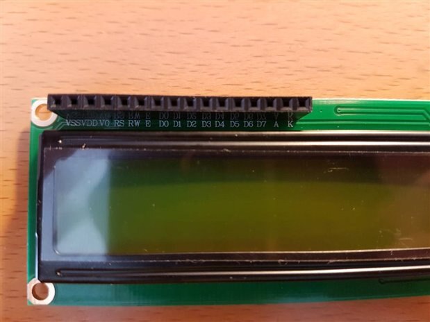
- the LCD display doesn't power up
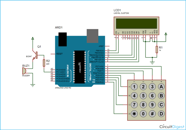
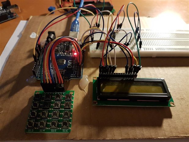
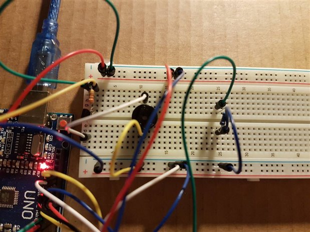
I've tried to lay the circuit out in a way that's straightforward to follow, but as I say, i'm pretty new to this. I found the circuit diagram hard to follow, as some of the connections shown differed slightly with my hardware (I tried to get as close to what the original poster listed as possible), especially the keypad. I suspect I've connected it up wrong, or put a component the wrong way round. I've dont some fault finding with my multi meter, and power seems to be getting to the components.
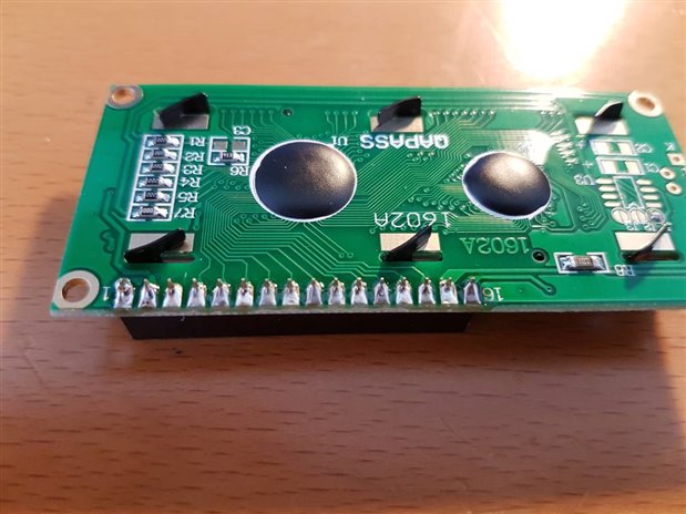
I've attached some images. Can anyone tell me firstly if it looks like I've connected it up wrong?
Message was edited by: Chris Swann - pictures added.
 | |
 |