element14 Community
element14 Community
    Register Log In
  • Site
  • Search
  • Log In Register
  • Community Hub
    Community Hub
    • What's New on element14
    • Feedback and Support
    • Benefits of Membership
    • Personal Blogs
    • Members Area
    • Achievement Levels
  • Learn
    Learn
    • Ask an Expert
    • eBooks
    • element14 presents
    • Learning Center
    • Tech Spotlight
    • STEM Academy
    • Webinars, Training and Events
    • Learning Groups
  • Technologies
    Technologies
    • 3D Printing
    • FPGA
    • Industrial Automation
    • Internet of Things
    • Power & Energy
    • Sensors
    • Technology Groups
  • Challenges & Projects
    Challenges & Projects
    • Design Challenges
    • element14 presents Projects
    • Project14
    • Arduino Projects
    • Raspberry Pi Projects
    • Project Groups
  • Products
    Products
    • Arduino
    • Avnet Boards Community
    • Dev Tools
    • Manufacturers
    • Multicomp Pro
    • Product Groups
    • Raspberry Pi
    • RoadTests & Reviews
  • About Us
  • Store
    Store
    • Visit Your Store
    • Choose another store...
      • Europe
      •  Austria (German)
      •  Belgium (Dutch, French)
      •  Bulgaria (Bulgarian)
      •  Czech Republic (Czech)
      •  Denmark (Danish)
      •  Estonia (Estonian)
      •  Finland (Finnish)
      •  France (French)
      •  Germany (German)
      •  Hungary (Hungarian)
      •  Ireland
      •  Israel
      •  Italy (Italian)
      •  Latvia (Latvian)
      •  
      •  Lithuania (Lithuanian)
      •  Netherlands (Dutch)
      •  Norway (Norwegian)
      •  Poland (Polish)
      •  Portugal (Portuguese)
      •  Romania (Romanian)
      •  Russia (Russian)
      •  Slovakia (Slovak)
      •  Slovenia (Slovenian)
      •  Spain (Spanish)
      •  Sweden (Swedish)
      •  Switzerland(German, French)
      •  Turkey (Turkish)
      •  United Kingdom
      • Asia Pacific
      •  Australia
      •  China
      •  Hong Kong
      •  India
      •  Korea (Korean)
      •  Malaysia
      •  New Zealand
      •  Philippines
      •  Singapore
      •  Taiwan
      •  Thailand (Thai)
      • Americas
      •  Brazil (Portuguese)
      •  Canada
      •  Mexico (Spanish)
      •  United States
      Can't find the country/region you're looking for? Visit our export site or find a local distributor.
  • Translate
  • Profile
  • Settings
Arduino
  • Products
  • More
Arduino
Arduino Forum Arduino and Transistors Question - RE: School Musical Production
  • Blog
  • Forum
  • Documents
  • Quiz
  • Events
  • Polls
  • Files
  • Members
  • Mentions
  • Sub-Groups
  • Tags
  • More
  • Cancel
  • New
Join Arduino to participate - click to join for free!
Actions
  • Share
  • More
  • Cancel
Forum Thread Details
  • State Verified Answer
  • Replies 126 replies
  • Answers 2 answers
  • Subscribers 402 subscribers
  • Views 7502 views
  • Users 0 members are here
  • raspberry
  • transistor
  • pi
  • arduino
Related

Arduino and Transistors Question - RE: School Musical Production

wallarug
wallarug over 11 years ago

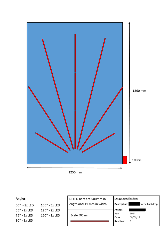
One of the directors has asked me to create a special backdrop for our college musical. This particular backdrop has a particular design (see below) that includes LED strip lighting to give the feel of a 1920s casino sign – similar to what is seen today in Las Vegas.

I  have done up a detailed design for this sign, based off the rough sketch given to me by the director and the dimensions of the backdrop.  On this diagram, the arrangement of the LED strip lighting can be seen.

image


The LED Strip lighting that will be bought for this project will be sourced from Jaycar – “Low Cost 5m Flexible Adhesive LED Strip Light – Warm White” (ZD0577).  According to the specifications off Jaycar’s website, these LED lights need 1.1 Amps per metre @ 12 volts.  This means that the longest segments of lights need 1.1 * 1.5 = 1.65 Amps of power (rounded up by 20% for safety: 2.0 Amps @ 12 volts).


This would not be an issue if I was just turning these LED Strips on and off with mains power BUT I want to control these LEDs via an Arduino, so that they can do fancy things like flash and chase.  That means that I would need a circuit to control these lights with an Arduino so that everything remains safe and does not blow up.

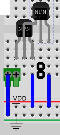
I have come up with this circuit (below) using a couple of NPN transistors and two power supplies.  In the diagram below, I am aware that the transistor pinouts are EBC.  The ones I am going to buy have a pinout of BCE.


image


The only problem with this is that I have very little understanding of transistor circuits.  What this circuit has to be able to do is:

  • Using the smallest amount of current from the Arduino (at 5 volts) or a Raspberry Pi (3v3 volts), turn on the circuit to allow the 12 volts that powers the LED strip lighting to flow.


I was thinking of using either TIP41C NPN Transistors (in a darlington Array) or TIP122 NPN transistors.


This circuit will be replicated 8 times over to accommodate for the number of LEDs I am controlling.


Can anyone help me:

  1. Design a circuit that will work 100% and will be safe (ie: low heat)
    1. This includes base resistance
  1. Confirm which transistors I should be using for this project.


Any help will be much appreciated.

  • Sign in to reply
  • Cancel

Top Replies

  • Robert Peter Oakes
    Robert Peter Oakes over 11 years ago +1
    Sorry the one I suggested wont work, but this one should http://www.jaycar.com.au/productView.asp?ID=ZK8821 10+ current rating and at 0.016ohms it should be good for your needs pdf here http://www.vishay…
  • mcb1
    mcb1 over 11 years ago in reply to jw0752 +1
    John If you are referring to this It means that at a gate voltage of 1.6 typ, a current of 250uA will be flowing in the Drain. If you look here, you can see that from 3 to 3.3v will give you enough to…
  • D_Hersey
    D_Hersey over 11 years ago +1
    Solenoid Whapper:
  • mcb1
    0 mcb1 over 11 years ago in reply to jw0752

    John

    No problems, its nice that we can learn something ... I know I haven't stopped.


    Mark

    • Cancel
    • Vote Up 0 Vote Down
    • Sign in to reply
    • Verify Answer
    • Cancel
  • wallarug
    0 wallarug over 11 years ago in reply to mcb1

    Hey Mark,


    Thanks for all your help.


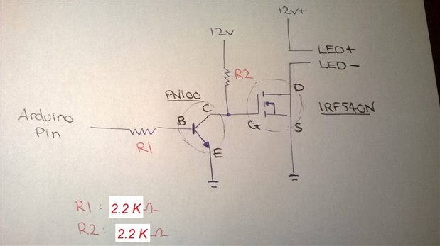
    Below is the up to date schematic.  From my understanding following this chain of posts, the circuit will be ON when the Arduino pin is set to OFF / 0 / LOW.


    Schematic with NPN transistor:

    image


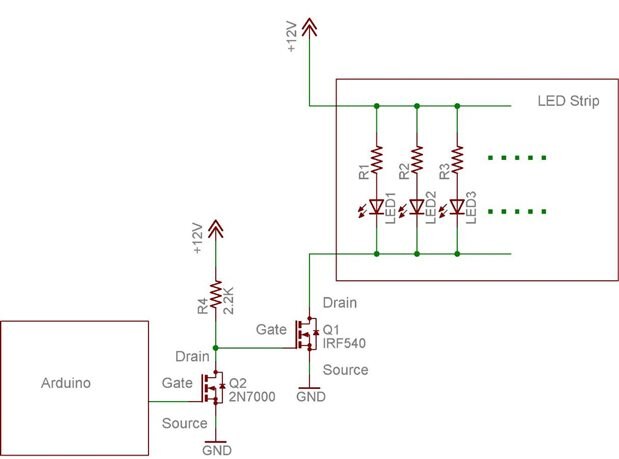
    Doug's CAD Schematic with MOSFET:

    image


    What I hoped to achieve by using the NPN transistor in this circuit was that I could have the Arduino output a HIGH to turn ON the LEDs.  Otherwise, the circuit that was posted earlier by Doug with the MOSFET would better as the MOSFET would draw much less current than the transistor and allow bigger loads to be controlled.


    Does anyone have any suggestions on whether I should go with the NPN or the MOSFET circuit?

    • Cancel
    • Vote Up 0 Vote Down
    • Sign in to reply
    • Verify Answer
    • Cancel
  • Robert Peter Oakes
    0 Robert Peter Oakes over 11 years ago in reply to wallarug

    If you use a logic level Mosfet (N Channel) then there is only one transistor needed and one resistor. Also a High Output would mean LED is ON


    Something like this http://www.redrok.com/MOSFET_HUF76137P3_30V_75.0A_9mO_Vth3.0_TO-220AB.pdf just put a 1K  in series with the gate to the Arduino


    but from JAYCAR http://www.jaycar.com.au/productView.asp?ID=ZK8821  should work, just in a different package and it contains two of them

    SI4944DY pinout,Pin outSI4944DY circuits.

    pdf here http://www.vishay.com/docs/72512/72512.pdf

    • Cancel
    • Vote Up 0 Vote Down
    • Sign in to reply
    • Verify Answer
    • Cancel
  • D_Hersey
    0 D_Hersey over 11 years ago in reply to wallarug

    Driving MOSFET with bipolar is typically a little slicker, else BiFet op-amps wouldn't be a thing.  A bipolar is a Current Controlled Current Switch, in this application, and a MOSFET is a Voltage Controlled Current Switch.  Putting a resistor in front of the bipolar turns it into a VCVS, at least that is the intent.  Using a shut-off resistor turns a MOSFET into a CCCS.  If you really wanted to get an LED to switch at 10 MHz, which you don't, you's probably need a push-pull scheme in order to deal with the load capacitances.  Martin C. Brown in his (excellent, BTW) Motorola book "Practical Switching Power Supply Design" inveighs against integrated gate drivers, claiming that an NPN/PNP push-pull totem-pole follower was always adequate at driving the MOSFET control terminal and always cheaper than an integrated gate driver.  Is your load going to be PWM-ed, or just switched?

    • Cancel
    • Vote Up 0 Vote Down
    • Sign in to reply
    • Verify Answer
    • Cancel
  • wallarug
    0 wallarug over 11 years ago in reply to D_Hersey

    I'd like it to do both PWM and Switched.

    • Cancel
    • Vote Up 0 Vote Down
    • Sign in to reply
    • Verify Answer
    • Cancel
  • Robert Peter Oakes
    0 Robert Peter Oakes over 11 years ago in reply to wallarug

    PWM and switched is basically the same thing


    what you may be thinking of is linear vs PWM, with linear you change the voltage to change the brightness, the problem with this though it the color quality of LEDs especially changes if you change the volts, and this is especially true with color leds. Also at a certain point the LED will simply shut off, it is not like an incandescent light where even the lowest voltages will be noticed.


    PWM "Switches" the LED on and off in order to give the illusion of changing the voltage (switching frequency is beyond visual range anyway so maybe 100Hz or more, often into the KHz), the idea here is that the LED is either full on or Full OFF. It is the ratio between on and off that gives the illusion of dimming the LED, the benefit is that the quality of the light output is maintained because the current through the LED is always at optimal (typically 20mA)


    in the circuits discussed above, in all cases we have been talking about a switch circuit, not a linear one, this is why the FET will not require a heat sink, it is either full on and therefor only presenting a few milliohms resistance or fully off so no current flowing. It is only the actual transition between on and off that will generate the most heat as the state passes through the intermediate resistance where significant current and volt drop is across the FET (Switch)


    if you switch too fast the FET will heat up, but you don't need to, only fast enough to not be noticed. The Arduino does not have Analog outputs, only logic levels, some of which can be connected to internal timers to help produce PWM. Others can simulate this using code if needed.


    Hope this help clarifies the intent.

    • Cancel
    • Vote Up 0 Vote Down
    • Sign in to reply
    • Verify Answer
    • Cancel
  • wallarug
    0 wallarug over 11 years ago in reply to Robert Peter Oakes

    Thanks Peter,


    All I really want to know is:  Will the circuit work as I want it too expressed throughout this forum post?


    1)  Switch ON LED strips (2 A @ 12 Volt)

    2)  ...with Arduino (5 volt)

    3)  ...low heat

    4)  .. able to PWM the outputs

    5)  and will not damage any equipment (either through heat / Amps / Volts)

    • Cancel
    • Vote Up 0 Vote Down
    • Sign in to reply
    • Verify Answer
    • Cancel
  • D_Hersey
    0 D_Hersey over 11 years ago in reply to Robert Peter Oakes

    If there is a difference between PMW and switched, it isn't electrical so much as physiological.  The issue isn't about the speed of circuits, but of the dyes in the eye and the speed of the visual cortex.  PMW attempts to use these delays to use the perceiver as an integrator.  At very slow speeds, MOSFETs are nearly ideal to control, go faster, we gotta reckon with the gate capacitance.

    • Cancel
    • Vote Up 0 Vote Down
    • Sign in to reply
    • Verify Answer
    • Cancel
  • mcb1
    0 mcb1 over 11 years ago in reply to wallarug

    Wallrug


    All I really want to know is:  Will the circuit work as I want it too expressed throughout this forum post?


    1)  Switch ON LED strips (2 A @ 12 Volt)

    Yes

    2)  ...with Arduino (5 volt)

    Yes

    3)  ...low heat

    Yes

    4)  .. able to PWM the outputs

    Yes in order to change the effective brightness..

    5)  and will not damage any equipment (either through heat / Amps / Volts)

    As long as nothing is damaged/destroyed or otherwise had the magic smoke let out.

    Using the dual mosfet or transistor / mosfet ensures that should there be some misadventure with Q1, the Arduino would not be impacted.


    I'm not sure why you are worrying about the output logic.... just deal with it in software.

    BTW you'll find the LEDs aren't linear with their brightness, so if its x bright at 100% duty cycle, then it won't be half as bright at 50%. ... but worry about that later.


    Mark

    • Cancel
    • Vote Up 0 Vote Down
    • Sign in to reply
    • Verify Answer
    • Cancel
  • wallarug
    0 wallarug over 11 years ago in reply to mcb1

    Thanks mate!


    That's all I needed to know!


    I'm not sure why you are worrying about the output logic.... just deal with it in software.

    I was really confused because there was different responses from different people.  But now that it has been clarified, I can go ahead with building it (probably next tuesday).


    Thank you all very much for your great and supportive help.


    • Cancel
    • Vote Up 0 Vote Down
    • Sign in to reply
    • Verify Answer
    • Cancel
<>
element14 Community

element14 is the first online community specifically for engineers. Connect with your peers and get expert answers to your questions.

  • Members
  • Learn
  • Technologies
  • Challenges & Projects
  • Products
  • Store
  • About Us
  • Feedback & Support
  • FAQs
  • Terms of Use
  • Privacy Policy
  • Legal and Copyright Notices
  • Sitemap
  • Cookies

An Avnet Company © 2025 Premier Farnell Limited. All Rights Reserved.

Premier Farnell Ltd, registered in England and Wales (no 00876412), registered office: Farnell House, Forge Lane, Leeds LS12 2NE.

ICP 备案号 10220084.

Follow element14

  • X
  • Facebook
  • linkedin
  • YouTube